Thanks for that reminder. Yes, I decided after talking with my friend this morning, I'll try to adjust it myself. If I run into trouble, I know I have a "safety net" in the form of my friend sitting down the hall from me. So far I have been blown away by how good this amp sounds.
I so much like the look of belly-isn compactrons. .. wondering if there is any similar looking octal one?
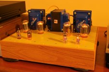
Thought I would post a picture of my stock build of the DCPP.
Nicely done. Great looking amplifier.
-D
The 6FW5 octal tube is virtually the same tube as the 6JN6 tube. Getting a little pricey lately, but not badly so. Also, 6DQ6B, if you want a plate cap on an octal base.
I've been enjoying the sound of this amp for several weeks now. I added a 100k ohm Alps volume control so I am no longer using the preamp section of my old Sanyo 75 receiver to control volume. But I am curious to try either the 6GU5 or the 6EW6 tubes in place of the 6CB6 tubes. Are both direct drop-ins? I have read through the thread and haven't seen mention of any modifications but just want to check to make sure.
Something I have been unable to find an answer for. Power pentodes such as the el34 normally last 1-2 years in an amp from what I have read. What is the life expectancy of a sweep tube such as the 6JN6 in this amp running around 50W?
What is the life expectancy of a sweep tube such as the 6JN6 in this amp running around 50W?
Good question. Haven't come across anyone running them at this level, and posting about it.
jeff
The 6JN6 has a design maximum rating for plate dissipation of 17.5 Watts.
You might not get very good life for a push pull amp that uses a pair of those to push out
50 Watts signal power.
The EL34 has a max plate dissipation rating of 25 watts.
The life you get is often dependent on how hard you push them (quiescent plate current and voltage, screen current and voltage, large signal operation, and amplifier mode: UL, Pentode, Triode wired).
i read somewhere that TV tube plate ratings are conservative since tv's are run for lot longer time than audio amps in most cases...
I think one can generally up-rate most TV Sweep tubes by 25 to 33% for an audio tube equivalent. 6JN6 has got similar plate area to a 25 Watt 807 tube.
The 18 Watt 21/6HB5 has got bigger plate area than most 6L6GC tubes. You could also put a bigger Sweep tube in the design with some socket/wiring fix-ups. (and more heater power) 6HJ5, 6DQ5, 6CB5, 22KV6, 21LG6A, 35LR6 ... for example. (those will do 75 to 100 Watts output easily with a low Zprimary OT, like 3.3K to 4K range, and bigger power xfmr)
The 18 Watt 21/6HB5 has got bigger plate area than most 6L6GC tubes. You could also put a bigger Sweep tube in the design with some socket/wiring fix-ups. (and more heater power) 6HJ5, 6DQ5, 6CB5, 22KV6, 21LG6A, 35LR6 ... for example. (those will do 75 to 100 Watts output easily with a low Zprimary OT, like 3.3K to 4K range, and bigger power xfmr)
Last edited:
You might not get very good life for a push pull amp that uses a pair of those to push out 50 Watts signal power.
If you were to crank 50 watt sine waves continuously, the tube life might not be so great......but I don't know anybody that likes that kind of music. Real loud highly compressed EDM usually has at least 10 db of peak to average ratio. Most other music is better. This means if you crank it up to where the music clips on 50 watt peaks, the overall average power is about 5 watts. Not going to hurt the tubes.
Just set the idle current somewhere below 13.5 watts or so per tube. 33 ma if you have 400 volts of B+. I run my 24 watt tubes on 30 ma at 600 volts.....they're still cranking.
I built the first 125 WPC version of this amp......mine still has the same tubes in it that I put there when I built it. I built 2 others....ditto.
TV tube plate ratings are conservative since tv's are run for lot longer time than audio amps in most cases..
The sweep circuit in a TV set has no volume control. It runs at full power ALL of the time. Most families had one, or maybe two TV's when these tubes were made. It did see a lot of use, more than the average HiFi set. Yes, the ratings on most sweep tubes are quite conservative.
But I am curious to try either the 6GU5 or the 6EW6 tubes in place of the 6CB6 tubes. Are both direct drop-ins?
Yes, although tweaking the plate load resistor value may squeeze a little more gain, if that's what you need. I never had any decent 6EW6's, so I never used them, but all 3 of my amps used 6GU5's as does Pete's monoblock version of my 125 WPC amp. They plug in place of the 6CB6 and provide a little more gain at lower distortion.
It seems to be difficult to get good 6EW6 tubes from used pulls. I ordered a bag of 35 of them, used pulls, and only 3 were decent. So I would make sure to get NOS or "tested" 6EW6 tubes. I suspect 6EW6s in radios didn't get replaced very often, so used ones are burnt to the ground. Probably just caused the weak stations to fade out.
I'm not familiar with 6BX6 or 6AM6 except just took a look at their datasheets.
6EW6 has got a nice low and sharp knee voltage around 50V versus more like 100V for those two. 6EW6 also has nice triode curves on the curve tracer, Mu 78-81. And high gm (14000). Oh, and the 6EW6 is quite happy with low g2 voltages like Sweep tubes use. It's rated for IF amplifier service, so could be microphonic. Pulls seem to be worthless though. Not very expensive tested or NOS from the big suppliers fortunately.
6EW6 has got a nice low and sharp knee voltage around 50V versus more like 100V for those two. 6EW6 also has nice triode curves on the curve tracer, Mu 78-81. And high gm (14000). Oh, and the 6EW6 is quite happy with low g2 voltages like Sweep tubes use. It's rated for IF amplifier service, so could be microphonic. Pulls seem to be worthless though. Not very expensive tested or NOS from the big suppliers fortunately.
Last edited:
smoking-amp,
Thanks for mentioning the famous 807.
The 807 has a continuous plate dissipation CCS rating of 25 Watts. But the Class C FM output may be 25, 32, 40, or even 54 Watts. That is because the 807 is working somewhat like a switcher; and the resonant tank circuit acts like a flywheel, and smooths the wave.
Yet the plate dissipation remains at 25 Watts.
For ICAS (interrupted service), the 807 plate dissipation rating is 30 Watts.
But that is far below the 40 or 54 Watts output from the RF amplifier.
I believe when a tube is used in sweep service, it also is working in Class C (on for less than 180 degrees). That is what makes the TV flyback work efficiently.
Yes, it does this continuously, at least until the station signs off, and you wake up and turn the TV off.
I once saw a sweep tube that ran so hot on one side of the plate, that the glass near it melted, and the vacuum pulled the glass in until it opened up and destroyed the tube.
But we probably do not want to run our audio amplifiers that way.
I believe when a tube is used in sweep service, it also is working in Class C (on for less than 180 degrees). That is what makes the TV flyback work efficiently.
Yes, it does this continuously, at least until the station signs off, and you wake up and turn the TV off.
There are two "sweep" tubes in a TV set. The vertical sweep tube, also called frame output, and the horizontal sweep, also called line output.
The TV's "picture tube" (CRT) contains an electron gun which shoots a stream of electrons at the inside face of the screen which is coated with a phosphor that will glow when zapped by a moving electron. The strength of the electron beam is modulated by the video output tube controlling the brightness of the glow. This makes a variable intensity dot in the center of the TV screen.
In order to paint a picture, we need to move, or "sweep" this beam across the face of the screen. This is where the term "sweep tube" comes from. There are electromagnetic coils mounted in a device called the "deflection yoke" or often just "yoke" on the neck of the CRT. When current flows through the coils in the yoke, the electron beam is bent to sweep the dot across the screen.
Enclosed is a chunk of a TV schematic from the late 50's showing the sweep output circuits. The vertical sweep output (6AQ5) is in the upper left. The horizontal sweep output (6CB5) and flyback transformer is lower center.
The vertical output tube is usually run in class A, and IS a linear amplifier capable of reproducing audio quite well. I made several audio amplifiers by lifting the entire vertical sweep circuit including it's OPT (T2 in the schematic) and replacing the feedback cap in the multivibrator (oscillator) circuit with an input jack. In a TV set it is responsible for sweeping the electron beam vertically on the screen. It has to be very linear in order for round things to apear round on the screen. A weak tube resulted in people with long legs and short fat heads. The drive signal is shown on the schematic. It is a linear ramp, bringing the tube from cutoff to full current to slowly sweep the beam (trace), then abruptly back to cutoff(retrace). The tube spends almost ALL of its time in conduction, and sees cutoff for a few microseconds while the beam quickly returns to it's starting place, it flies back (again the origin of the name). This is a color TV, so the vertical output tube also drives some "convergence" circuitry to ensure that the right color phosphors are being struck by the right electron beam (1 beam in a B&W TV, 3 in color).
The horizontal sweep circuit is much more complex, since it has several more jobs to do. As with the vertical output, the horizontal sweep tube sweeps the beam left and right. The tube is driven deeper into cutoff during retrace to ensure that the current in the FLYBACK (horizontal OPT) is completely cutoff resulting in a voltage spike similar to that in an automotive ignition coil. This is stepped up to a high voltage (like a car coil) and rectified by the HV rectifier (3A3) to produce 25 KV for the CRT. It also produces 1 to 2 KV for the beam focusing electrode in the CRT via the focusing rectifier (1V2). The entire flyback circuit rings at its self resonant frequency (100 to 200 KHz) and that energy is rectified by the damper tube which is in series with the B+ supply. This action bootstraps the B+ to the 6CB5 up to 660 volts (BOOST B+). Again the tube sees conduction for nearly ALL the time, retrace time is a few microseconds.
Both sweep circuits run full power all the time regardless of what's on the screen.
Attachments

Tubelab_Com,
Thanks for the reminder of the way the analog TV sweeps work.
My age is showing.
You also reminded me of the waveforms, which tell the story.
I worked on a medical 'printer' that printed out a single frame of a TV image of the imaging doppler.
In order to keep the sweep current linearly increasing, the voltage had to rise very quickly at first because of the yoke inductance. There was a sense resistor in series with the ground end of the yoke, and this signal was used so negative feedback could be applied to the horizontal amp.
The printer used a 'Line' CRT, so there was so little inductance in the vertical yoke that I do not think there needed to be any sense resistor and negative feedback for the vertical amp.
Last edited:
- Home
- Amplifiers
- Tubes / Valves
- Posted new P-P power amp design