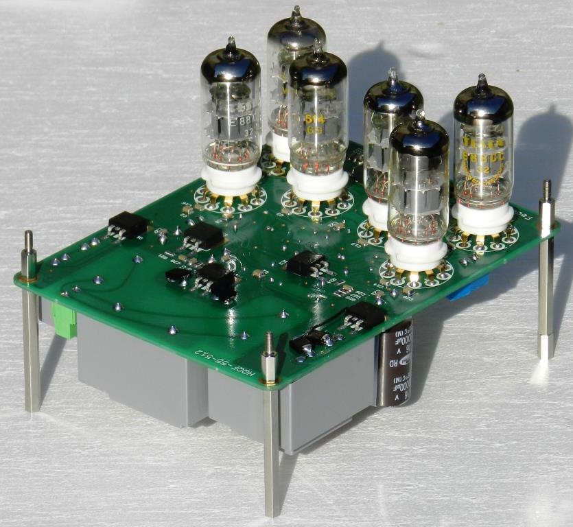
Balanced preamp tube

Have you listened to it yet? If yes, how do you describe de sound signature.
Thanks
Do
Hi Bonsai,
Could you PM me the link to where the PSU modif is and the modding you are talking about on the amps boards?
Thanks
Do
Sorry, I only saw this Question right now.
Here is a link to the errata doc covering both amplifiers and PSU +Protect
http://hifisonix.com/nx-amp/updates-and-errata-nx-amplifier/
I just built a second nx-Amp 2 weeks ago with Jims Audio boards and the updates per the errata sheet. Works perfectly.
Uncharacteristically, I am going to blow my own trumpet here: this is an awesome sounding amp (I'm using B&W 703's, my X-Altra mini preamp and an Oppo BD-103 player).
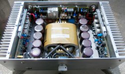
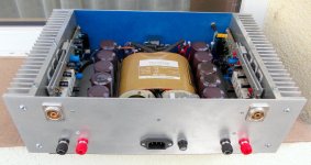
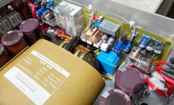
Power transformer is 500 VA, with belly band and inter winding screen.
Last edited:
So this is my first DIY amp, it's a finals project for one class.
It's a part of my bachelor degree in becoming an Electronic Technician.
I tried my best, there are alot of flaws that i have learned alot from and my next amp will be twice as better... I hope. Maybe a better cooling unit is required but i'll fix that later, i have to show it to the bachelor comittee on friday so i have no time.
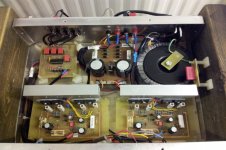
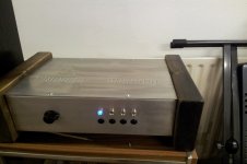
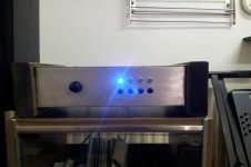
The front is very basic, it has a Volume control and four buttons to switch between four channels.
The Circuit in the top left corner is the PIC input selector.
It consists of one PIC chip(obviously), four Mosfets to drive the relays, flyback diodes, pullup resistors and of course the DPDT Relays with gold coated contacts.
I'm rather proud of that design. One problem with it tough, there is a minor signal leakage between the channels when i send a very strong signal in. It needs improvements but it's good for a first effort i guess.
The chassis is made and designed by me, the PSU is designed by me and the input selector circuit is designed by me, but the amplifier is designed by Naldo Santos(link below).
http://www.diyaudio.com/forums/solid-state/238768-amplifier-hifi-ns450-200w.html
It's a part of my bachelor degree in becoming an Electronic Technician.
I tried my best, there are alot of flaws that i have learned alot from and my next amp will be twice as better... I hope. Maybe a better cooling unit is required but i'll fix that later, i have to show it to the bachelor comittee on friday so i have no time.
The front is very basic, it has a Volume control and four buttons to switch between four channels.
The Circuit in the top left corner is the PIC input selector.
It consists of one PIC chip(obviously), four Mosfets to drive the relays, flyback diodes, pullup resistors and of course the DPDT Relays with gold coated contacts.
I'm rather proud of that design. One problem with it tough, there is a minor signal leakage between the channels when i send a very strong signal in. It needs improvements but it's good for a first effort i guess.
The chassis is made and designed by me, the PSU is designed by me and the input selector circuit is designed by me, but the amplifier is designed by Naldo Santos(link below).
http://www.diyaudio.com/forums/solid-state/238768-amplifier-hifi-ns450-200w.html
Attachments

Last edited:
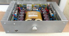
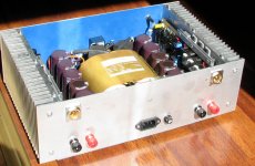
Is the power toroid securing bolt
Isolated on the bottom side.
Nice project, you should be proud,
Always nice to create something of your own.
Regards
Isolated on the bottom side.
Nice project, you should be proud,
Always nice to create something of your own.
Regards
Maybe a better cooling unit is required
Two tips for that one:
- drill holes also in the bottom plate under the heat sinks
- change the heat sinks into ones with vertical fins, so then the air convection will pull the air from the under side and the warmer air has a straight path up and out of the enclosure
Anyway nice looking project.
Is the power toroid securing bolt
Isolated on the bottom side.
Regards
No it's not, i have the ground pin on the AC Plug connected to the bolt on the transformer.
Does that create some problems?
Does that create some problems?
It creates a majour ground loop around your entire system.
Can easily burn the whole HOUSE up with smoke and fire.
Last edited:
It creates a majour ground loop around your entire system.
Can easily burn the whole HOUSE up with smoke and fire.
How exactly can that cause a fire?
Hallmar hope you don't mind the comments on your lovely project.
But its better to take the Mains earth to the chassis and not to the top of the toroid mounting bolt.
The bottom of the bolt is connected to the chassis and is therefore grounded already.
So don't connect anything to the top of the bolt.
Placing another ground on top of the bolt causes a "shorted ground wire winding" through and around the toroid,
This should be avoided.
Regards
Last edited:
Hallmar hope you don't mind the comments on your lovely project.
But its better to take the Mains earth to the chassis and not to the top of the toroid mounting bolt.
The bottom of the bolt is connected to the chassis and is therefore grounded already.
So don't connect anything to the top of the bolt.
Placing another ground on top of the bolt causes a "shorted ground wire winding" through and around the toroid,
This should be avoided.
Regards
Oh please, do come with comments.
I'll fix that when i get the chance 🙂
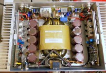
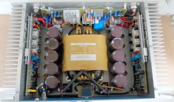
Very impressive how you've laid this out internally and made use of the space. Hope it sounds as good as it looks!
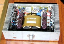
Thank you all for comments ,and realy sound very clear ,no hum , hiss ,buz . I'm glad I have built 🙂
My speakers are Taga Harmony Platinum F-120, and more pictures
My speakers are Taga Harmony Platinum F-120, and more pictures
Attachments
Thank you all for comments ,and realy sound very clear ,no hum , hiss ,buz . I'm glad I have built 🙂
My speakers are Taga Harmony Platinum F-120, and more pictures
Well done! Great work Mr!!! Amazing construction - so clean... 😎
Thank you all for comments ,and realy sound very clear ,no hum , hiss ,buz . I'm glad I have built 🙂
My speakers are Taga Harmony Platinum F-120, and more pictures
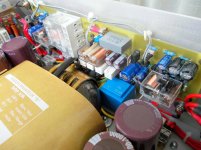
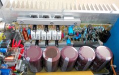
You might have fake caps ... nippon chemicon kmh 100v@10k are much larger.
Those might just be 80V/4700uF relabled units.
Member still4given just had one of those caps explode @ 80V rails !!! 😱
ps- if they measure 50 X 100mm .. they might be genuine.
If you sourced from ebay/alibaba - they might not be ?
OS
Last edited:
Thank you all for comments ,and realy sound very clear ,no hum , hiss ,buz . I'm glad I have built 🙂
My speakers are Taga Harmony Platinum F-120, and more pictures
your placement and overall packaging and wiring is supreme!
You might have fake caps ... nippon chemicon kmh 100v@10k are much larger.
Those might just be 80V/4700uF relabled units.
Member still4given just had one of those caps explode @ 80V rails !!! 😱
ps- if they measure 50 X 100mm .. they might be genuine.
If you sourced from ebay/alibaba - they might not be ?
OS
😉 Doesn't matter it has a lot of total capacitance. The amplifier has a +-55V , maybe smaller voltage supply.
- Home
- Amplifiers
- Solid State
- Post your Solid State pics here