could you inform me with some information about your transformer?AB class mono amp with all protection
warm regards
andrew
v2=?
I=?
Hi Soheil95
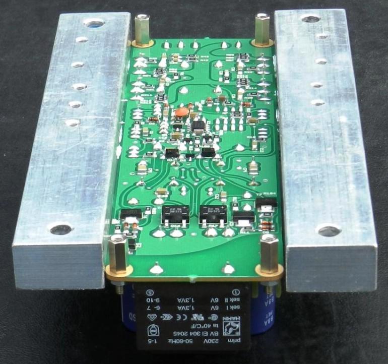
greetings transformer secondary AC 65 O 65 2 transformers in parallel 2 50 ampere bridge rectifiers parallel
warm regards
Andrew
greetings transformer secondary AC 65 O 65 2 transformers in parallel 2 50 ampere bridge rectifiers parallel
warm regards
Andrew
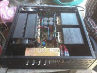
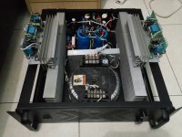
That's one sweet cabinet.
Thanks, I have a lot of time involved in machining and building the cabinets. I hope to be listening to them sometime this weekend.
Not anything particularly new, and some contributors own work on here is excellent, but here is my now rather aged Musical Fidelity P170.
Uprated RATA 15000uF PS caps
Metallised polypropylene Kimber Kaps
RATA Supersound capacitors
Philips axial electrolytics
Vishay resistors.
Ian
An externally hosted image should be here but it was not working when we last tested it.
Uprated RATA 15000uF PS caps
Metallised polypropylene Kimber Kaps
RATA Supersound capacitors
Philips axial electrolytics
Vishay resistors.
Ian
Member
Joined 2009
Paid Member
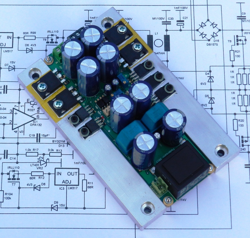
Project started last year , but I will finish soon 🙂
Alex
I noticed something special, the insulators between power devices and heatsink. I think I know why you have them - can you say where / how you got them ?
They're called ceramic substrate (no mounting hole)
(e.g. a 22mmx28mm size in 3mm or 4.5mm thickness costs ~$1-$1.20/pc +tax for a hundred minimum order)
(e.g. a 22mmx28mm size in 3mm or 4.5mm thickness costs ~$1-$1.20/pc +tax for a hundred minimum order)
Member
Joined 2009
Paid Member
ceramic insulators transistors | eBayI noticed something special, the insulators between power devices and heatsink. I think I know why you have them - can you say where / how you got them ?
Are those supposed to insulate electrically, or thermally????
Do you know if these are made from Beryllia? If so, please be extremely careful if you use them since chipping or cracking one will produce a toxic dust.
I've always used SIL pads myself, mostly for the convenience, no paste required, but actually some types are very low thermal impedance.
I've always used SIL pads myself, mostly for the convenience, no paste required, but actually some types are very low thermal impedance.
From beryllium oxide to be exact. BeO dust dangerous but in such concentration as at plants. Best ceramics for transistors has a pink color maybe it Al2O3Do you know if these are made from Beryllia? If so, please be extremely careful if you use them since chipping or cracking one will produce a toxic dust.
I've always used SIL pads myself, mostly for the convenience, no paste required, but actually some types are very low thermal impedance.
For high electrical insulation and for high thermal conduction.Are those supposed to insulate electrically, or thermally????
and is it true that they affect the sound ?
You're joking, right ?
Beauty of a forum, the answer is never far away => www.diyaudio.com/forums/pass-labs/121228-f5-power-amplifier-281.html#post3908184
I don't think he is joking.
Temperature will have an effect on performance.
The question becomes:
Will the temperature difference between different cooling methods become audible?
Temperature will have an effect on performance.
The question becomes:
Will the temperature difference between different cooling methods become audible?
Mr. Borin's design uses 230W bipolar OnSemi devices in the output stage (4302/4281).
http://oi43.tinypic.com/104ffi0.jpg
Alex picked Sanken power transistors with higher fT (A1303/C3284 ?), but those are 125W Pd devices.
By using oversized Al2O3 substrate insulators and clamping the power devices at the die center-line, he can compensate some of the 0.456 C/W difference in thermal resistance.
Last edited:
Member
Joined 2009
Paid Member
I don't think he is joking.
It's worse than you thought - I have seen two commercial amplifiers where it was claimed that having large 'eddy current' conductors near the signal path was detrimental. The power amp had thick insulators like shown above, the other was a pre-amp and the casework was all perspex with no metal.
- Home
- Amplifiers
- Solid State
- Post your Solid State pics here