Anyway whats the point of 30+30V on the outputs when the maximum rail to rail swing from opamp is less than half the supply voltage... If the outputstage had gain of 2 it would work well but it needs couple of more components and perfomace will drop..
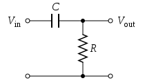
This pic is basic circuitpost3635:
the pic shows input impedance = 52k (51k+1k).
Not 100k.
The gain is shown as 51 (1+50k/1k).
Not 20.
Did you build what you have posted?
I adapted
Ex.
input
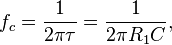
4.7 uf /1k Frequency Cutoff Frequency 33.9 Hz
Res.
10uf /1K Cutoff Frequency 15.9 Hz
-----------------
Overall, there is a basic circuit
I adjusted my style.
It would be more helpful to post what you built along with what you thought of the result.
It is not helpful to post what you did not build along with what you thought of what you did build !!!
BTW,
f = fempto
F = Farad.
It is not helpful to post what you did not build along with what you thought of what you did build !!!
BTW,
f = fempto
F = Farad.
This pic is basic circuit
I adapted
Ex.
input
4.7 uf /1k Frequency Cutoff Frequency 33.9 Hz
Res.
10uf /1K Cutoff Frequency 15.9 Hz
-----------------
Overall, there is a basic circuit
I adjusted my style.
4.7uF sees 1k+51k as the filter and rolls off at ~ 0.65Hz.
Changing to 10uF lowers the F-3dB to ~0.3Hz.
Did you hear any difference?
Did you measure any difference?


Nixies / lamps = bleeding noise from the power supply rails = great idea 😎
Those are cool little lamps, what are they called? ...i.e. how do i find them.
I can't tell for sure. Nixies (glow lamps/pilot lamps) or something else. Hopefully attalostesla will enlighten us.
??

??
(The idea, I think, is to react to any 60 hertz (or other) ripples, removing some of the "hum" on the power supply rails = less noise. Those lamps are apparently in parallel with the "bleed" resistors on the PS = blocking DC, reacting to AC.)
Last edited:
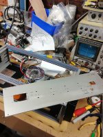
Aren't those LEDs mounted under the fuses?
Yeah, those are definitely LEDs mounted under the fuses. No harm there.
Do
orange and green LEDs under the fuse, 🙂Yeah, those are definitely LEDs mounted under the fuses. No harm there.
Do
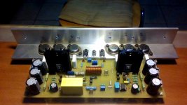
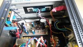
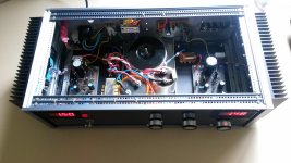
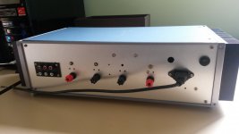
My P68 with 8 output transistors, supply pcb with DC protection/delay and Diyaudio soft-start.
An externally hosted image should be here but it was not working when we last tested it.
An externally hosted image should be here but it was not working when we last tested it.
An externally hosted image should be here but it was not working when we last tested it.
An externally hosted image should be here but it was not working when we last tested it.

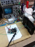
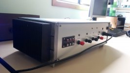
My Class A amp
Pure class A based on the "death of zen spec" 54 watts dissipation for 15 watts rms output into 8 ohms per channel.
Pure class A based on the "death of zen spec" 54 watts dissipation for 15 watts rms output into 8 ohms per channel.
Attachments
-
 20140912_115216.jpg434.4 KB · Views: 388
 -
 20140912_110934.jpg539.1 KB · Views: 413
 -
 20140912_110908.jpg581.5 KB · Views: 475
 -
 20140912_110856.jpg504.4 KB · Views: 418
 -
 IMG_20140714_124008.jpg527 KB · Views: 317
 -
 IMG_20140716_144810.jpg657.1 KB · Views: 298
 -
 20140912_115304.jpg937.3 KB · Views: 281
 -
 20140912_115250.jpg886.8 KB · Views: 369
 -
 20140912_115032.jpg719 KB · Views: 482
 -
 20140912_123238.jpg601.1 KB · Views: 401
Last edited:
Pure class A based on the "death of zen spec" 54 watts dissipation for 15 watts rms output into 8 ohms per channel.
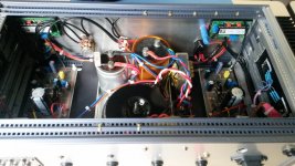
Construction though is very very wrong
The #1 thing that you don't do is to twist the cables and even more worst tie together the 3leads of a NPN and PNP output transistor ..."heavy" currents flowing there in C and E of each transistor will interact at some point with the B
Bad practice
- Home
- Amplifiers
- Solid State
- Post your Solid State pics here