I have measured a Meanwell LPV-100-24 with a spectrum analyzer (SA) by using the DC LISN from Elektor, which provides 50 Ohm outputs on plus and minus. These outputs go into either a 0° combiner (ZFSC-2-4) or a 180° combiner (ZFSCJ-2-1, minicircuits) for measuring either the differential or the common mode noise. The input of the SA is attenuated by 30dBm in total, band width was 300Hz, the LISN goes from 150kHz to 200MHz. The load of the SMPS is 1.84A (24V DC).

=> All the noise is differential noise, apparently no contribution from common mode noise.
The switching frequency is around 70kHz (distance between spikes), from the noise pattern (distance of minima) the degree of PWM modulation could be calculated.
The apparently decreasing noise floor below 500kHz is due to the filters of the LISN and the transient limiter in front of the SA. A measurement of the DC voltage at the output of the SMPS with a 16-bit scope (AC coupling, +/-20mV resolution, bandwidth limited to 200kHz, Gaussian filter,) shows ample noise below 1MHz.

Thanks for posting. I'm not sure one can deduce from the 1st measurement that there is no common mode noise. WIth 50 Ohms in series with each leg into the combiner, you've effectively balanced the output first, a condition which doesn't exist in use. The 2nd graph makes more sense. If plotted on a log freq scale, it is very much consistent with others posted here.
Great thread jbau although you have shattered all my sweat dreams on SMPS.
Thanks J-P, mine too. Though I haven't given up yet, just taking a bit of a break from the bench.
? The 180° splitter inverts the phase of one leg relative to the other leg. If a common mode signal is present in both lines, the signal shows up, whereas with the 0° combiner the CM signal is fully cancelled (and the differential signals show). Correct?I'm not sure one can deduce from the 1st measurement that there is no common mode noise. WIth 50 Ohms in series with each leg into the combiner, you've effectively balanced the output first, a condition which doesn't exist in use.
@jean-paul: Regarding the use of this SMPS for audio: Never, ever... Even after filtering it wont be silent enough. I just wanted to know about the amounts and kinds of noise.
? The 180° splitter inverts the phase of one leg relative to the other leg. If a common mode signal is present in both lines, the signal shows up, whereas with the 0° combiner the CM signal is fully cancelled (and the differential signals show). Correct?
Not "signal", voltage. With the 50 Ohms in the ground leg, what were ground-contaminating currents (low-impedance) are now voltages which apparently cancel in your 50Ω splitter transformer (although the switching freq fundamental and 2nd harmonic are below the sweep start freq). A 50Ω system wouldn't be my choice to evaluate this sort of thing. Short out the 50Ω in the LISN (-) leg and try it.
Another POV: Your "common mode" noise curve shows about -95dB (is it dBV? dBm 50Ω?) at sweep start (150kHz). Assuming it's dBV, if we add 6db for the 50Ω division, and 30dB for the attenuator, -95 + 6 + 30 = -59dB, which is certainly not "no common-mode noise"... it's in the same ballpark, maybe even worse, than the filtered outputs that I was measuring.
But if it is not commom-mode noise, then you should be able to deal with it using simple passive filtering and be happy, yes?@jean-paul: Regarding the use of this SMPS for audio: Never, ever... Even after filtering it wont be silent enough. I just wanted to know about the amounts and kinds of noise.
My bet is, the LPV-100-24 is no better than the other retail switchers.
Not "signal", voltage: Agreed.
"ground-contaminating currents": No, these measurements are done following the CISPR 25 standard. The LISN I use is described here:
https://www.elektor.com/elektor-dual-dc-lisn-150-khz-200-mhz
TekBox offers a CISPR 25 single line LISN, therefore you would need two of them. Connecting the outputs of both LISNs to the TBLM1 LISN-mate (done in my measurements with the 0° and 180° combiners) distinguishes then between DM and CM noise.
"Ground" has in these measurements little to no meaning, as we measure fully differential voltages (going into 50 Ohm).
A nice application note from Analog Devices shows on how both emissions are measured with the splitters I also used:
https://www.analog.com/en/analog-di...emissions-in-conducted-emissions-testing.html
This note shows also that the LISNs are the same for DM and CM measurements, but the combiners differ (see figure 3 in this note).
Regarding the filtering: I havent had time to make some and measure them, but in the near future...
For me it is more important to know that no CM noise will be radiated from the LED chain. What needs to be measured additionally, are the emissions of the SMPS into the mains, but for this I need a LISN such as the TBLC08.
For those who are not so familiar with this topic, maybe a few words about why using a line impedance stabilization network (LISN)?
A voltage itself tells us little about the energy per time behind it, because its only a potential difference. For the emissions, however, the power is important (given usually in dBm, the m referring to the reference power of 1 mW). Therefore, we need additionally either the current or we need to know the impedance, into which the voltage induces a current and use then Ohms law. For making measurements comparable, it is necessary to know either both voltage and current or we have constant impedance and measure the voltage and recalculate this to power into 50 Ohm (done with the spectrum analyzer). All the CISPR standards use a constant 50 Ohm, which is established with the LISN for a specified frequency range.
Hope this helps a bit🙂
Last edited:
Not "signal", voltage: Agreed.
"ground-contaminating currents": No, these measurements are done following the CISPR 25 standard. The LISN I use is described here:
https://www.elektor.com/elektor-dual-dc-lisn-150-khz-200-mhz
That is not a setup I would choose for measuring smps output noise in and above the audio band, which is the purpose of this thread. It is for measuring conducted emissions from the DUT input, not the power supply output.
"Ground" has in these measurements little to no meaning, as we measure fully differential voltages (going into 50 Ohm).
Yes, ground has no meaning in these measurements, but it sure does when connecting an smps to an analog audio system.
All the CISPR standards use a constant 50 Ohm, which is established with the LISN for a specified frequency range.
Interesting, but not really relevant for this. Besides what I noted above, it's lower limit is 150kHz. That alone makes it an interesting side dish but not the main course.
BTW, specs say the LISN attenuation is 10dB so that makes the LPV-100-24 measured CM noise even worse, more like -55dB.
Over the decades there have been LISN's used for conducted dc compliance measurements from 9kHz upwards, although as I recall most are related to uncommonly seen or applied standards, but may well be part of compliance for any dc port in a wide variety of equipment - and so CISPR 25. I'm not across the most recent widely known standards and only have CISPR 22. The ANSI/IEEE C63.4 link below seems to include relevant LISN info for 9 to 150kHz. I think it is well worth trying to align testing with available standards, although unless someone is directly across a broad range of the latest standards, and has access to such standards, then it is likely quite difficult to get a fair and balanced view on the topic.
https://citeseerx.ist.psu.edu/docum...&doi=1aa6476a25b4bed755dec85f0bc132400877da0d
https://citeseerx.ist.psu.edu/docum...&doi=1aa6476a25b4bed755dec85f0bc132400877da0d
@trobbins: Fully agree with you and I would be happy to see the range below 150kHz as well, but: I am not doing some official EMI precompliance testing here (this would require devices and equipment orders of magnitude more expensive than I have;-), my aim here was to check the following: What kind of noise (DM, CM) is present and at what level. Without knowing this, attempts to minimize this noise would be cumbersome.
Meanwhile I got my internal preamp for the SA, which lowers the noise floor of the SA by about 20 dBm (@jbau: the noise floor shown in my first figure above stems essentially from the SA).
I remeasured the SMPS with exactly the same conditions (the 10dB attenuation of the LISN is included in the 30dBm total attenuation), and now my statement above (CM does apparently not contribute) is changed to: It does, but on a very low level relative to DM noise.

Please note the Y-scale, which differs from the figure above, it goes 20dBm lower.
The bottom trace is the noise of the SA attached to the setup, but the SMPS is off.
So the next step should be designing a filter to get rid of this noise.
@jbau: Regarding the noise within the audio band: I would be much more concerned with the noise in the MHz region (and above), because it is this frequency range, which ingresses into the audio chain and deteriorates its performance. Ask someone who does HAM radio; these guys can tell you more (and how cables act as antennas).
Meanwhile I got my internal preamp for the SA, which lowers the noise floor of the SA by about 20 dBm (@jbau: the noise floor shown in my first figure above stems essentially from the SA).
I remeasured the SMPS with exactly the same conditions (the 10dB attenuation of the LISN is included in the 30dBm total attenuation), and now my statement above (CM does apparently not contribute) is changed to: It does, but on a very low level relative to DM noise.
Please note the Y-scale, which differs from the figure above, it goes 20dBm lower.
The bottom trace is the noise of the SA attached to the setup, but the SMPS is off.
So the next step should be designing a filter to get rid of this noise.
@jbau: Regarding the noise within the audio band: I would be much more concerned with the noise in the MHz region (and above), because it is this frequency range, which ingresses into the audio chain and deteriorates its performance. Ask someone who does HAM radio; these guys can tell you more (and how cables act as antennas).
Thanks for this link, highly interesting!
Agree in general. But I don't think we want to make this even more difficult for forum folks to participate in by upping the ante equipment- and procedure-wise. We have to KISS. It's difficult enough getting everyone to present the data in the same way so that at-a-glance comparisons can be made.@trobbins: Fully agree with you and I would be happy to see the range below 150kHz as well, but: I am not doing some official EMI precompliance testing here (this would require devices and equipment orders of magnitude more expensive than I have;-), my aim here was to check the following: What kind of noise (DM, CM) is present and at what level. Without knowing this, attempts to minimize this noise would be cumbersome.
Meanwhile I got my internal preamp for the SA, which lowers the noise floor of the SA by about 20 dBm (@jbau: the noise floor shown in my first figure above stems essentially from the SA).
I remeasured the SMPS with exactly the same conditions (the 10dB attenuation of the LISN is included in the 30dBm total attenuation), and now my statement above (CM does apparently not contribute) is changed to: It does, but on a very low level relative to DM noise.
Thanks, your new measurement is making more sense.
And note that the freq scale is MHz, not kHz as shown.Please note the Y-scale, which differs from the figure above, it goes 20dBm lower.
So the next step should be designing a filter to get rid of this noise.
That has been my focus.
@jbau: Regarding the noise within the audio band: I would be much more concerned with the noise in the MHz region (and above), because it is this frequency range, which ingresses into the audio chain and deteriorates its performance. Ask someone who does HAM radio; these guys can tell you more (and how cables act as antennas).
My dad was a ham and a genius with antennas. In retrospect, I probably should have paid more attention to what he was doing... I can look out a north window and see two local radio station transmission towers, one AM, one LPFM. So I am keenly aware of RF issues. But I don't put it as #1 priority. If a power supply performs poorly in the audio band, it gets booted regardless of its RF immunity or generation.
Back to the measurements and KISS. Since the switching freq fundamental noise is typically 20dB higher than the harmonics, it HAS to be included in the measurement. And HAS to be top priority in the filtering.
It's fairly easy to see what the level of CM noise is. When normal diff mode filtering ceases to reduce the noise, what remains is the common-mode noise. You can see in my measurements this was typically around -80 to -84dBV at the fundamental freq. How does this compare to your measurement? Add the 30dB LISN + SA attenuation to the Y scale of your CM noise plot and voila it is very much the same.
So while I appreciate the results with the LISN + SA setup, this work can be done without the use of specialized equipment (I have spectrum analyzers that go up to 1GHz but have not bothered to use them for that reason).
Thus far, using a common-mode choke + filtering on the output is the only thing that has moved the needle in the right direction. In my opinion, it is not yet good enough to be used on its own for high-quality audio, but it will continue to be where my efforts will go.
Good questions. My guess is, most sound cards have capacitor-coupled inputs. Check yours and and see what their voltage rating is, and polarity. My guess is, most use small 'lytics with (+) to the input. Otherwise, you have to put an appropriate capacitor in series with the input. For a 22kΩ input, 10uF is fine, and 35-50V would cover most uses.
With 20-24bit ADC's, I bet you'lll have enough dynamic range to get useful measurements without needing a preamp.
I've been loading either 50% of rated max or 1A, mostly because that is what my current application is.
With 20-24bit ADC's, I bet you'lll have enough dynamic range to get useful measurements without needing a preamp.
I've been loading either 50% of rated max or 1A, mostly because that is what my current application is.
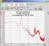
I did some experiments today using the XP Power smps tested first in this thread, chosen because it is easily the noisiest smps I've measured. I wanted to see what difference, if any, a CM choke with low leakage inductance makes. And compare them both to no CM choke. And I expanded the measurement bandwidth to 500kHz to see noise beyond the first two harmonics.
The first plot is with the same PE-62912 CMC I've been using, with a 1500uF 20mΩ ESR cap on the load side. The PE is rated 3mH but measures closer to 4. It has nearly 60uH of leakage.
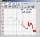
The second plot is a bifilar-wound 450uH CMC which only has 400nH of leakage, followed by the same 1500uF cap.
The third plot is with no CMC, just the 1500uF cap.
Besides still concluding that this power supply really sux for audio, it is clear that the differences between these three configurations is not dramatic. The CM chokes are not delivering a significant amount of common-mode attenuation. The 3mH CMC has the lowest overall noise, but the 2nd harmonic at 100kHz is actually no different than with just the cap on the output. The low-leakage CMC is a little better above 100kHz but not hugely so.
The other point is that, like other smps I have measured, the switching freq and its 2nd harmonic are by far the worst offendors, by 20dB or more. Except this model also has that unusual 1.5kHz noise spike.
The first plot is with the same PE-62912 CMC I've been using, with a 1500uF 20mΩ ESR cap on the load side. The PE is rated 3mH but measures closer to 4. It has nearly 60uH of leakage.
The second plot is a bifilar-wound 450uH CMC which only has 400nH of leakage, followed by the same 1500uF cap.
The third plot is with no CMC, just the 1500uF cap.
Besides still concluding that this power supply really sux for audio, it is clear that the differences between these three configurations is not dramatic. The CM chokes are not delivering a significant amount of common-mode attenuation. The 3mH CMC has the lowest overall noise, but the 2nd harmonic at 100kHz is actually no different than with just the cap on the output. The low-leakage CMC is a little better above 100kHz but not hugely so.
The other point is that, like other smps I have measured, the switching freq and its 2nd harmonic are by far the worst offendors, by 20dB or more. Except this model also has that unusual 1.5kHz noise spike.
Attachments

For me, the spectrum does not look like a pulse-width modulated square wave (cf. my picoscope measurement above). Do you have an oscilloscope to have a look on the actual waveform? Maybe this would give a hint about the origin of this strange 1.5kHz peak?The other point is that, like other smps I have measured, the switching freq and its 2nd harmonic are by far the worst offendors, by 20dB or more. Except this model also has that unusual 1.5kHz noise spike.
@Grauwacke Your testing was without external filtering, no? This is an oscilliscope (Cleverscope). The 1.5kHz waveform is the dominant time-domain component. But that's not the point here. The highlight is the relative ineffectiveness of the CMC.
I used an oscilloscope with a bandwidth of 5MHz, but I switched on the 200kHz limiting in the scope to avoid aliasing.
- Home
- Amplifiers
- Power Supplies
- Post you SMPS noise spectrum measurements