So that measurement was with no load on the SMPS (i.e. after the filter) ?No, this peak does not come from averaging in the scope, it is the noise (smoothed somewhat due to averaging). In a single shot the bumps are already there.
IMHO, the shift of the bumps comes from the changing impedance the SMPS sees at the output, when the filter is inserted between output and load. This changes the pulse width modulation accordingly.
Both measurements were with load (LED chain), the blue trace without the LC filter, the red one with filter in between.
The scope (AC coupled) was directly connected to the leads going into the LED chain. So no attenuation as in the spectrum analyser measurements.
Maybe a short explanation, what the averaging in the scope does: It measures the frequency range within several seconds (depends on the number of bins and frequency range), calculates the Fourier transform and measures and calculates again and so on. So the individual FFTs are summed and normalized to the number of measurements. For uncorrelated noise the standard deviation on a point reduces more and more, the trace gets smoother. This process does not introduce any peaking or other artefacts, it just minimizes the noise of the measurement.
Nice thread. I’m trying to design a mains filter to absorb this sort of stuff. So the worst offender here has only -40dB to -50dBV rms noise? Thats in the several to ten mV rms?
I would have thought SMPS can inject several volts into the mains or is that just too large?
I would have thought SMPS can inject several volts into the mains or is that just too large?
If you consider to be compliant with EMC regulations, you should look at the limits allowed on the ac-outlets. Conducted emissions normally are measured between 150khz and 30MHz. With limits in the mV-region. Quite different from noise relevant in the audio band.
They are worried about RF noise. We are worried about audible noise. Most SMPS and Class D’s are 60kHz to 400kHz or 1MHz. Although these are beyond hearing, I think they can result in beat frequencies with each other in the kHz range. And if mV are allowed, what are levels of non compliant stuff?
I’m thinking of concentrating on 1kHz to 1 MHz noise sources.
I’m thinking of concentrating on 1kHz to 1 MHz noise sources.
"They are worried about RF noise."
This is a very loose specification to start with. Reminds me of debates about distortion of certain passive components.
Anyway this depends totally on the noise susceptility of the audio equipment and other circumstances. Which may vary widely.
Furthermore it makes a big difference considering common mode or differential mode noise. I see many people here focusing on differential mode noise - which is only part of the truth. I have been working professionally as EMC expert for decades and all I can say is you have to define the acceptable limits first as your design goal. Consider your noise source, the coupling mechanism and the noise susceptability of your equipment. Wild addition of filters without verification is a waste of resources.

Good to know you are a pro in this field. I do mean to test. I am thinking of a case (anecdotal) is a power outlet strip (unfiltered) that I have a linear headphone amp plugged into. The moment I connect a cheap SMPS (one of those LED drivers into it, or a small 5V USB charger) I hear noise in the previously quiet headphone amp. What is that coupling mechanism ? I think the SMPS is probably lacking a blocking cmc filter on its power inlet. The noise it makes bleeds back on the power strip and maybe into the rest of the house. How does one simulate this on LTspice?
This is a typical case. Specially for audio it makes a big difference between a 2-prong wall wart and a 3-prong labtop brick or similar 3-prong SMPS. The 2-prong SMPS has y-caps between primary DC-circuitry and secondary dc-circuit to tame rf noise sent to ac-line. These caps with typical 1~5nF conduct some 100uA ac current. This is not pure 60Hz current - but full wave rectified 60Hz, that is 120Hz full distorted. Which makes this much more annoying noise than 60Hz sine wave. By nature this is a common mode noise, any secondy LC-filter will help - nothing at all! There is a common mode noise current coming from the wall, with a well noticable spectrum in the audio, that will seek its way to ground earth, via capacitive coupling. Long, unscreened wiring of sensible audio are affected by such leakage currents.
Bottomline is - you cannot filter the common mode noise emanating from 2-prong SMPS, because this would require common-mode chokes of very high impedance - measured at 120Hz. Connecting secondary circuit to PE solves this problem.
On the other hand you can design audio circuitry of high immunity against leakage noise currents by using short paths of interconnects, low impedance paths and simple screening of interconnects.
Last edited:
I just bought (this thing) an hour ago. Got the 1000 Watt model. I'm thinking it will greatly attenuate any common mode noise on the mains, and prevent (most of!) it from entering into the downstream audio gear. (link 2 to more specs).
If one places all the dirty SMPS in the input side mains and connect the clean low noise audio gear on the other side of the balanced PSU filter mentioned above, would not a large balanced toroidal trafo block any noise from getting through? Reminds me of one of those huge CorePower units.
@bucks bunny - are you saying all one needs to do is connect the secondary (2 prong) circuit low side to a PE ground and that will solve the noise from the Y2 cap filter induced ground loop? Wouldn’t a GLB be good to use here? 10ohm or NTC with a 22nF in parallle to ground.
@bucks bunny - are you saying all one needs to do is connect the secondary (2 prong) circuit low side to a PE ground and that will solve the noise from the Y2 cap filter induced ground loop? Wouldn’t a GLB be good to use here? 10ohm or NTC with a 22nF in parallle to ground.
You are right, exactly that is what I am saying. As the coupling mechanism is a common mode current source (1nF driven by several hundred volts of 120Hz sinoids) a small series resistor would do no harm at all and may prevent from 60Hz hum loops. What is GLB?
@bucks bunny "Wild addition of filters without verification is a waste of resources."
I would like to know how you measure common mode noise technically at mains frequencies and above?
I would like to know how you measure common mode noise technically at mains frequencies and above?
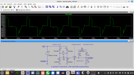
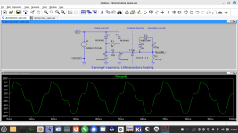
Staying in my 2-prong scenario as described above. The common mode noise is here a leakage current. High frequency leakage current is measured with a current clamp around the entire bundle of primary or secondary cables using a high sensitive broadband spectrum analyzer. For the audible leakage we are talking you can measure leakage current simply using any good AC-current measuring DVM inserted between floating secondary output and PE-GND. In the simulation this corresponds to an AC-current meter instead of 10R resistor (R2). You will read something in the ballpark of 50..100uA rms. With a direct PE-connection of the secondary circuitry this current is diverted from the meter and its readings drops to zereo. It is really simple like that.
Just a couple of observations about SMPS from my playing around with them:
Quiet ones are quiet because the switching action is smooth: but a badly designed and/or implemented one would radiate such noise that was impossible to get rid of, regardless of the filtering I tried.
Sometimes some chinese factories omit the secondary noise suppression (which of course makes quiet supplies, even quieter) so when you order from eBay etc I'd recommend not buying the cheapest one, often they have cutr corners in my experience. You can always retrofit this though I guess.
Also, sometimes they age, I had a Seagate remote disk PSU fail once, only later did I repurpose the 12V adapter and find that it dumped huge noise into the mains which my audio amplifiers picked up, but it was outputting a horror show at about 9V.
That was when i decided to look on the scope at my other 12V disk supplies, and found one had 1V spikes on it, another was pretty quiet, and a Huawei was super quiet - so that got chosen for the backup disks 😀
I had solid results with this one (comes with NUC11). Not better than the linear power supply I built to power up my NUC, but okay copared to other SMPSs I tried.

Also, sometimes they age, I had a Seagate remote disk PSU fail once, only later did I repurpose the 12V adapter and find that it dumped huge noise into the mains which my audio amplifiers picked up, but it was outputting a horror show at about 9V.
That was when i decided to look on the scope at my other 12V disk supplies, and found one had 1V spikes on it, another was pretty quiet, and a Huawei was super quiet - so that got chosen for the backup disks 😀
Well done. That's the most overlooked issue with SMPS noise. Everyone seems to just be looking to put a filter post the SMPS...
- Home
- Amplifiers
- Power Supplies
- Post you SMPS noise spectrum measurements