Alright, just to demonstrate that common-mode chokes can reduce noise substantially if used appropriately, here's the same wall-wart from post #38, with the same 2A load, this time with a choke and capacitor between it and the load.
I can't tell you a part number for the choke because it's just a random one I had in my parts drawer. It measures 2.2mH common-mode, 8.6µH differential-mode @ 100kHz. DCR is 0.05Ω (both windings in series). The capacitor is a standard 1000µF 35V part, with an ESR of 35mΩ @ 100kHz.
The switching noise at 120kHz is gone completely, and the noise floor has been pushed down quite a lot.
Attachments
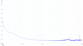

Actually, it's not completely gone... it's at -84dBV, which is in the same ballpark that I was getting.
Your noise floor is definitely lower, though.
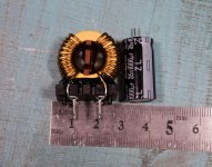
Can you post a pic of the choke? That will give us some bearings on it.
Also, for clarity, pls explain how you're measuring the inductances.
Your noise floor is definitely lower, though.
Can you post a pic of the choke? That will give us some bearings on it.
Also, for clarity, pls explain how you're measuring the inductances.
Last edited:
Here you go, one photo of a choke, plus the capacitor I used.
I measured the inductance with a DE-5000. Connect the windings in series, and reverse the polarity of one winding to switch between differential and common mode.
I measured the inductance with a DE-5000. Connect the windings in series, and reverse the polarity of one winding to switch between differential and common mode.
There's something at -84dBV, but it's not the switching frequency. It could be a harmonic, but given how much less it has been attenuated than everything nearby, I suspect it's actually radiated interference that has been picked up, perhaps from my poorly shielded PC.Actually, it's not completely gone... it's at -84dBV, which is in the same ballpark that I was getting.
Attachments
Click on "See details", it's just the 9V adapter... the price of the meters hasn't changed.
Last edited:
Here you go, one photo of a choke, plus the capacitor I used.
Thanks, my 3.1uH choke is pretty much the same.
I measured the inductance with a DE-5000. Connect the windings in series, and reverse the polarity of one winding to switch between differential and common mode.
Same here. I wasn't getting a reading that made sense after reversing the polarity of one winding. I was measuring at 1k, though. Will try higher.
There's something at -84dBV, but it's not the switching frequency. It could be a harmonic, but given how much less it has been attenuated than everything nearby, I suspect it's actually radiated interference that has been picked up, perhaps from my poorly shielded PC.
Ah, right, my bad. Your switching freq is down around -92, which is about the same as I was getting with the 3.1uH choke and 1000uF. This suggests to me that we may be in the right ballpark already.
The value of CM choke looks like the important variable here, so I set up to model this last night, but my circuit analysis pgm doesn't support diff outputs, only ground-referred. So I'll have to do it the hard way, build and measure. Fortunately CM chokes are easy to "make". Just take a toroid choke with 1-layer winding of about 3 times the diff inductance you want, snip the center of the winding, and voila, instant common-mode choke. 👍 The commercial ones make it look official by inserting a vertical plastic divider.
Methinks an analyzer with diff inputs might be nice too... still working on that. May be not a big deal for audio, since in use one side will be grounded.
BTW, with 16 bits you should still be able to get 20dB or so more dynamic range. Is your input range set high? You can knock it down to 100-200mV.
Last edited:
500mV, which is what I had to set it to for the unfiltered measurement before, and I wanted the two measurements to be as comparable as possible.BTW, with 16 bits you should still be able to get 20dB or so more dynamic range. Is your input range set high? You can knock it down to 100-200mV.
The 5444D isn't the quietest 'scope though; I was a bit disappointed that it's noisier than the 4262 that I used to use.
Sidelined for a few days with flu, back at it again.
Here's the attenuation curve for the two CM chokes I've been playing with. My assumption is, we want a large cap on the output side, so a 1000uF cap is there. I wanted to see the difference between the chokes in differential vs common mode. And in particular, I wanted to see a reason why the 60uH CMC had 10dB less attenuation at 65kHz than the 3.1uH one did.
Here's the 3.1uH curves.

And here is the 60uH one.

Common mode configuration definitely gives more attenuation, 5 to 10dB.
However, I don't see why, as I measured a few days ago, the 60uH had 10dB less attenuation of the 65kHz switching freq than the 3.1uH did. These curves say it should have been about 8dB more than the 3.1uH. Any ideas?
BTW, I'm calling these by the inductance of one side, not with both windings in series. If the latter is the correct way, then these are actually 6.2uH and 120uH CMC's.
So there's more to figger out here. The 3.1 definitely needs to be about 3 times larger inductance to be effective at 65kHz.
Here's the attenuation curve for the two CM chokes I've been playing with. My assumption is, we want a large cap on the output side, so a 1000uF cap is there. I wanted to see the difference between the chokes in differential vs common mode. And in particular, I wanted to see a reason why the 60uH CMC had 10dB less attenuation at 65kHz than the 3.1uH one did.
Here's the 3.1uH curves.
And here is the 60uH one.
Common mode configuration definitely gives more attenuation, 5 to 10dB.
However, I don't see why, as I measured a few days ago, the 60uH had 10dB less attenuation of the 65kHz switching freq than the 3.1uH did. These curves say it should have been about 8dB more than the 3.1uH. Any ideas?
BTW, I'm calling these by the inductance of one side, not with both windings in series. If the latter is the correct way, then these are actually 6.2uH and 120uH CMC's.
So there's more to figger out here. The 3.1 definitely needs to be about 3 times larger inductance to be effective at 65kHz.
Makes sense, but does that explain it?
Edit: I was expecting to see a V-shaped response of the choke's L with the C.
Edit: I was expecting to see a V-shaped response of the choke's L with the C.
Last edited:
They do stuff like that a lot.Click on "See details", it's just the 9V adapter... the price of the meters hasn't changed.
Makes sense, but does that explain it?
Edit: I was expecting to see a V-shaped response of the choke's L with the C.
Dunno, maybe a simulation to compare the measurements with would help.
Also don't know why there is a peaking, and faster cutoff, with the 60uH.
Maybe has to do with the core materials and losses.
Here's something from Coilcraft that looks like it might help. Haven't looked into this before though.
https://www.mouser.com/pdfDocs/doc191_CMFiltDesign.pdf
https://www.mouser.com/pdfDocs/doc191_CMFiltDesign.pdf
Thanks Ray, I'll study that this evening.
Meanwhile, here's some progress. A 15uH (per side) CMC is giving better (-38dB) attenuation depth at 65kHz, but even more above 100kHz.

After seeing this, I'm thinking there may be something wrong with the 60uH one. It's an outlier, so far.
Meanwhile, here's some progress. A 15uH (per side) CMC is giving better (-38dB) attenuation depth at 65kHz, but even more above 100kHz.
After seeing this, I'm thinking there may be something wrong with the 60uH one. It's an outlier, so far.
I hadn't noticed before, but some of the 60uH's windings are under a layer of tape and the layers overlap.
Last edited:
I tried a 1500uF cap with the 15uH choke and it was worse.
So smaller cap and larger choke is needed to get the null closer to 65kHz.
Here's the 15uH with 680uF, and a 28uH with 680uF. Note the vertical scaling has changed to accomodate the greater attenuation. Definitely heading in the right direction, though some peaking has returned. More to come.

So smaller cap and larger choke is needed to get the null closer to 65kHz.
Here's the 15uH with 680uF, and a 28uH with 680uF. Note the vertical scaling has changed to accomodate the greater attenuation. Definitely heading in the right direction, though some peaking has returned. More to come.
These are very good sources of information on noise reduction in all circuits; applies to SMPS as well.
https://pearl-hifi.com/06_Lit_Archi...Electromagnetic_Compatibility_Engineering.pdf
https://commons.princeton.edu/motor...sites/70/2019/08/otto_1988_noisereduction.pdf
Hal
https://pearl-hifi.com/06_Lit_Archi...Electromagnetic_Compatibility_Engineering.pdf
https://commons.princeton.edu/motor...sites/70/2019/08/otto_1988_noisereduction.pdf
Hal
OK, I finally found a CMC that has a part number and found the data sheet for it, so I can measure and compare this one and see how they spec these things. It's a Pulse Engineering PE-62912 . Second one down in the spec chart.
https://www.mouser.com/datasheet/2/447/plei_s_a0001291382_1-2903857.pdf
It is spec'ed as the inductance of one winding, not both in series. In this case, 3mH. This one measures closer to 4.
I am even more convinced that these high-inductance CMC's are not suitable for SMPS output filters. The output impedance would be insane. PE even says in the data sheet "For use in switching power supply input filter circuits". 3mH is ok if you're only passing current at 50/60 Hz. For a power supply output, low-uH is appropriate.
Further, the inductance quadruples when connected in series (diff) but drops like a rock when it is connected in common mode configuation.
Anyway, just thought I'd pass that info on, in case you find or make one. They're quite easy to make.
- Home
- Amplifiers
- Power Supplies
- Post you SMPS noise spectrum measurements