The "suitable meter" reads a tad higher than that because it is flat to beyond 100kHz and -3db closer to 300kHz.
There's nothing wrong with the measurements being presented here, I don't understand why you're making a big deal about it.
There's nothing wrong with the measurements being presented here, I don't understand why you're making a big deal about it.
No big deal - just for confidence - and as would often be done when posting measurements (eg. identification of meter used, and capability or measurement setup) in a technical forum. It is not easy to make such measurements, and I'd anticipate few have voltmeters that are flat to beyond 100kHz (although many would for signals up to circa 1kHz). I'm concerned that some will post results that have measurement gremlins in them, without the poster appreciating they have an issue, and that may then be enough to persuade others from using such equipment.
Will do this tomorrow with my ancient treasure, an HP3577a analyzer.
I have one too... you have a DC blocker for it, I hope...
Here's another one to avoid. A variable voltage, selectable polarity plugin switcher, ProTechTrader brand. Probably bought on Amazon. I have used this for its versatility, mostly on the test to power the Mega328 transistor tester, Fluke handheld DMM's, etc.
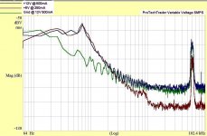
At 12V @ 500mA (blue trace), it's OK-ish. At 6V and below @ 250mA (brown trace), it's better. What bothered me, though is that it ovverloaded the inputs even at 100mV RMS FS. So I decided to check for ground noise. The green trace is with the supply loaded at 12V @ 500Ma, with probe tip and ground lead connected to its "ground" output.
Above 2kHz ALL of the noise on the output is on the ground side. I checked a couple other small plugin switchers and their output ground was much cleaner, only some of the switching frequency appearing on it.
Certainly not recommended for audio. And methinks I'll go back to using the analog variable-output wallwart on the bench.
Attachments
The Mean Well RPS series enjoys a pretty good reputation on this forum. I was really hoping that someone that owns one would measure theirs and post the results. So I bought one that is comparable to the XP Power unit first measured, though with a lower noise spec. This unit is a Meanwell RPS-30-15, 15V @ 2A output. If it works out, it will be put to good use.
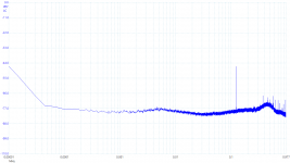
I loaded it with 15 Ohms and measured the RMS AC output in a roughly 300kHz bandwidth at whopping 17.84mV. Ouch. Yes, it's better than the 100mVP-P spec, but worse than almost everything else I've measured. There was no change with the - output being earthed.
Here's the 100kHz output noise spectrum. There's a spike in the upper midrange, just like the XP Power though lower in amplitude, this one at ~3.5kHz. And the 60kHz switching freq is quite high at 2.5mV. So this means that most of the noise is above 100kHz.

I'm not impressed by this, and wouldn't recommend it for high-quality audio use. It certainly won't be going into my electrostatic headphone amp.
So far the only smps I've measured that would be good for audio are the Boschert and Volgen industrial switchers, and the little HG Power plugin.
Another one bites the dust.
I loaded it with 15 Ohms and measured the RMS AC output in a roughly 300kHz bandwidth at whopping 17.84mV. Ouch. Yes, it's better than the 100mVP-P spec, but worse than almost everything else I've measured. There was no change with the - output being earthed.
Here's the 100kHz output noise spectrum. There's a spike in the upper midrange, just like the XP Power though lower in amplitude, this one at ~3.5kHz. And the 60kHz switching freq is quite high at 2.5mV. So this means that most of the noise is above 100kHz.
I'm not impressed by this, and wouldn't recommend it for high-quality audio use. It certainly won't be going into my electrostatic headphone amp.
So far the only smps I've measured that would be good for audio are the Boschert and Volgen industrial switchers, and the little HG Power plugin.
Another one bites the dust.

So now it gets interesting, and we get to see how effective filtering the output is.

The yellow curve is the stock RS30-15.
The cyan curve adds a 1,000uF 20mΩ 'lytic (Panasonic FM) on the output. It lowers the noise above 3kHz, and lowers the 60.7kHz switching freq by some 30dB. The 3.5kHz spike is lowered by some 17dB. Respectable, but not excellent.
The magenta curve adds a 0.5Ω resistor between the +V out and capacitor. The 1000uF cap has .5Ω impedance at around 350Hz so we should see additional noise reduction from about 300Hz and up, increasing with frequency. The switching freq spike should be reduced by 28dB compared to the cyan curve. Markers were set at 60.7k on all traces.
And what do we see? Noise does indeed decrease above 300Hz, but there is NO REDUCTION in the switching freq spike. None at all.
Why? Because the switching noise appears on both outputs at the same phase.
Low-pass-filtering the output by adding additional series impedance, either with R or L or a combination of them, and then "dumping it to ground" with the C is going to have no effect. The switcher noise will take the low impedance path provided through the capacitor and appear on the output. And, your circuit ground will be contaminated with it.
Both outputs need to be filtered to reduce the switching noise. This calls into question the effectiveness of the multi-stage RLC filters suggested earlier in this thread.
Such filters need to be measured with an actual SMPS, not just computer-modeled. It would certainly help if measurement data was provided with them.
In fact, such a filter is most likely detrimental if it feeds an audio circuit directly, because it makes the supply's output impedance incredibly nonlinear.
Last edited:
"Low-pass-filtering the output by adding additional series impedance, either with R or L or a combination of them, and then "dumping it to ground" with the C is going to have no effect. The switcher noise will take the low impedance path provided through the capacitor and appear on the output. And, your circuit ground will be contaminated with it."
... that's exactly what I found and the main reason why I decided not to pursue SMPS in audio applications any more.... I used my ears
The reason for the above is the implementation of that ring choke on the SMPS board - it is inserted between the dirty ground and the output ground. In other words, there is no ground potential of a low-noise nature (low impedance at high frequencies) that could be used to dump the noise into -> that darn choke works in both ways (!! 🙂)
Thanks for sharing your findings.
... what might work is using a higher impedance choke.... keeping in mind that the current consumption will be depending on the low DC-resistance of this choke... which in other words would most definitely require an off-the-board mounted choke. I was so close to trying this.... but didn't...
Exactly!!Exactly right, Boky. And even if used as "raw DC" or pre-regulator and followed by a good analog regulator, the switching noise is high enough in freq that it passes right through the regulator unattenuated. Once it's on the circuit ground, it's everywhere.
Be sure to tell the dozens of B1 Korg builders with an SMPS and single sided filter: "You are WRONG! That filter CANNOT POSSIBLY improve the sound. Your BIAS has polluted your listening experience!"
Be sure to tell the same thing to the dozens of ACP+ builders with an SMPS and single sided filter.
Be sure to tell the same thing to the 100+ builders of RACAM (Round Amp Camp Amp Monoblock) with an SMPS and single sided filter.
Make sure you scream "YOUR EARS ARE WRONG AND I AM RIGHT." People find that sort of discourse, irresistibly compelling.
Any louder and it will leak through the thread walls 😀
There's a theory that having a system contaminated with 60kHz is kinda like AC bias in analog tape recording. It "stirs things up" and "gets things moving". No doubt there's a "just-right" amount of it.
I don't buy it, but the theory exists.
There's a theory that having a system contaminated with 60kHz is kinda like AC bias in analog tape recording. It "stirs things up" and "gets things moving". No doubt there's a "just-right" amount of it.
I don't buy it, but the theory exists.
In addition, output filtering does nothing to curb the mains-side pollution of SMPSes - which you won't measure until and unless you have at least one other audio piece of gear in the same chain.
I have to agree with jbau. I have measured these single sided filters and they have little impact mostly due to the reason jbau explained (polluted circuit ground). I also tried adding common mode chokes to these filters with no noticeable improvement. These filters are ineffective in removing 50Hz related noise but of course it is possible that in some cases filtering just higher frequency noise is sufficient to improve the sound.Be sure to tell the dozens of B1 Korg builders with an SMPS and single sided filter: "You are WRONG! That filter CANNOT POSSIBLY improve the sound. Your BIAS has polluted your listening experience!"
...
You need a common-mode choke to deal with that of course. I had to do that with a switch-mode bench PSU: https://www.diyaudio.com/community/threads/taming-a-noisy-smpsu.327778/...Why? Because the switching noise appears on both outputs at the same phase...
Anyway, since no one but jbau has posted any measurements so far, I'll contribute something. This is a JT-TP238C1U1 65W GaN USB-PD charger. It's hard to say who made it, because they are sold under many brands. It's small enough to come in the "wall-wart" form-factor, and weighs only 108g. I haven't opened it up to look at the circuitry, but it's good quality as far as I can tell - certainly able to output its rated 65W while only getting slightly warm.
This is the sort of PSU I use these days for low-power devices like portable class-D amps. Being able to adjust the output voltage makes them conveniently universal, and the efficiency is very high.
I used a USB trigger cable to set it to 12V, and applied a 6Ω load. Bear in mind that the cable is 1m long, and there's no capacitor at the end, so it will pick up some extra noise. It's unavoidably earthed via the 'scope.
I took the measuerment with a PicoScope 5444D, a 1x probe, 977kHz FFT bandwidth (annoying that it can't be set to exactly 1MHz), 65536 bins, Blackman window, 32 average.
The switching frequency is clear at 120kHz. There are some harmonics higher up, outside the range of the chart. No mains frequencies visible. Total ripple is 35mV rms (20MHz bandwidth).
Attachments
Thanks for posting a measurement, @Mr Evil . The switching spike at about -48dBV is pretty typical, as is the total ripple. I'm wondering about the noise floor at only -77dBV. Was your 5444D in 8-bit mode?
I have a selection of common mode chokes here , I'll experiment with them this week. If it works, it would probably be acceptable to use for the output of an AC>DC converter / preregulator. But I doubt I'd want to use one to directly power a circuit, esp. power amp. My hunch is the output impedance would not look good. I'll make some measurements to confirm.
I have a selection of common mode chokes here , I'll experiment with them this week. If it works, it would probably be acceptable to use for the output of an AC>DC converter / preregulator. But I doubt I'd want to use one to directly power a circuit, esp. power amp. My hunch is the output impedance would not look good. I'll make some measurements to confirm.
They work, we all know that.You need a common-mode choke to deal with that of course. I had to do that with a switch-mode bench PSU: https://www.diyaudio.com/community/threads/taming-a-noisy-smpsu.327778/.
Have you tried to use the common mode choke in an SMPS at the output (low-voltage) end? Give it a go and see how successful the SMPS start-up will be...
Last edited:
- Home
- Amplifiers
- Power Supplies
- Post you SMPS noise spectrum measurements