Won't build so for sale
If some one is interested in a full set.
I have one that I have never came to build please PM if interested
Peter
If some one is interested in a full set.
I have one that I have never came to build please PM if interested
Peter
Hello again.
Now, I´m ussing all transformer, 18-0-18V (realy isn´t symetrical, I purchased the chipest) The current must be higher because I have been forced to put heashinks. Sorry but I didn´t take meters. The sound is better.
I´ll don´t looking for another preamplifier for my JELabs 300B. Maybe if some day I finish the pumpink...
It will be worth test xlr input with SE amplifier? Of course, my dac have xlr output.
Best regards
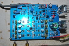
Problem with current through jmp 01
Hello.
I turned on the pcb 01 and don´t is ok.
The measures are 17,70v PSU, The middle leg of Q3 2,33V. The red led shine ok, but the problems be the Q7 is very hot even with heatshink and open P1 and with main potentiometer in 5 o´clock the curren in jmp 01 is only 5,77mA
with jumper 01 put it the minimum current through jumper 02 is 40mA.
¿Can anybody tell me where could be the problem?
Best regards
I´m not sure if understand you ok.
I don´t put LM317 right because the datasheet is diferent of LM317L.
My LM317 is T0-220 with 1,5A
I don´t put LM317 right because the datasheet is diferent of LM317L.
My LM317 is T0-220 with 1,5A
pcb is made for LM317 ; I didn't wrote suffix , but it's written in table as : IC1 -LM317- 1A5 - T0220
so - no need for twisting legs !
so - no need for twisting legs !
He he. Looks nice. In Mouser
WV-T220-101E Ohmite | Mouser
If don´t run put: 588-WV-T220-101E
Are you find any mistake?
WV-T220-101E Ohmite | Mouser
If don´t run put: 588-WV-T220-101E
Are you find any mistake?
Jose,
Where did you get that PCB?
Regards zeoN_Rider
Hello Zeonrider
I bought ZM some years ago.
Do you test any LDRs volume control?
Best regards
problem is that you twisted legs of IC1 , without reason
I saw Adj-in-out but I think is for other package.
In one old version of schematics put LM317L
I would never put 317L for that current
He he I take in my hands at this moments.
- Home
- Source & Line
- Analog Line Level
- Poor Serbian Man Optical Volume Control