Hi ZM, if kits are still available, can I have a stereo balanced and buffered one please, plus the matched J Fets. Thanks 😀
Hi ZM, if kits are still available, can I have a stereo balanced and buffered one please, plus the matched J Fets. Thanks 😀
yeah - Itsyou - you can reach me at >sasica5@gmail.com<
ZM, Please send me a PM with the truck numbers´ packet.
Thanks.
Jose - I tried few ways of tracking these days , but I didn't succeeded having anything more than info about day when package left Serbian borders ; reason is simple - Serbia isn't part of EU ;
anyway - let's wait few days and - if you don't receive package , I'll send you new one . piece of mind ( your and mine ) is more important than $$ and value of packages .
yeah - Itsyou - you can reach me at >sasica5@gmail.com<
Jose - I tried few ways of tracking these days , but I didn't succeeded having anything more than info about day when package left Serbian borders ; reason is simple - Serbia isn't part of EU ;
anyway - let's wait few days and - if you don't receive package , I'll send you new one . piece of mind ( your and mine ) is more important than $$ and value of packages .
Ok. I´ll wait. Thank you very much for your effort ZM.


anyway - what I wrote :
should be nothing else than peace of mind .........piece of mind
kwayzee ZM .........
( anyway - I'm sometimes having problems on our local Serbian forum - switching from this DiyA to Serbian one ..... I'm still posting there - on English ..... )
Last edited:
How long does deliver to US take?
Its been 5 weeks since I paid for a board package, and my recent email inquiry is unanswered.
Its been 5 weeks since I paid for a board package, and my recent email inquiry is unanswered.
Comment by wabun on Today
Sorry as I still have another doubt, the split power supply which use LM317 for +ve and LM337 for -ve rails constant current source has different current output, although I constructed them with 22Ohms current limit resistor, but I got ~ 46mA at +ve rail and ONLY ~ 16 mA at -ve rail. By calculation I shud get ~ 56mA from each rail.. why this happen ? :-( tot LM337 faulty, but still the same even replaced with new IC.. I measure the current by connecting 100 Ohms resistor ( serial to ammeter)
and shorted the output ( LM 337 / LM317 ) reference to ground.. thanks
Comment by wabun on Today
Sorry as I still have another doubt, the split power supply which use LM317 for +ve and LM337 for -ve rails constant current source has different current output, although I constructed them with 22Ohms current limit resistor, but I got ~ 46mA at +ve rail and ONLY ~ 16 mA at -ve rail. By calculation I shud get ~ 56mA from each rail.. why this happen ? :-( tot LM337 faulty, but still the same even replaced with new IC.. I measure the current by connecting 100 Ohms resistor ( serial to ammeter)
and shorted the output ( LM 337 / LM317 ) reference to ground.. thanks
Hi, PCB02 supply schematic is attached here. Current capability is defined by Vref/Rx or Vref/RY where Vref = 1,25V. Why You shorted Regulator ref to gnd?
Attachments
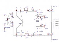
Rx or Ry to be 220 Ohms (if I understood well) is not good value. 1,25V/220 = 5,6mA current capability.
In http://www.national.com/ds/LM/LM337.pdf You will see (page 6) that maximum allowed is 120 Ohms. Explanation good enough for LM317 is provided here Constant current source with LM317
Best Regards, sp300b
In http://www.national.com/ds/LM/LM337.pdf You will see (page 6) that maximum allowed is 120 Ohms. Explanation good enough for LM317 is provided here Constant current source with LM317
Best Regards, sp300b
trick with this PSU is floating CCS for zenner string
it will work as planned - with symmetrical load , what you'll have with implemented buffers
Slobo - I mean that wabun used 22 Ohms , but wrote 22Ohms
it goes well with mentioned 56mA
it will work as planned - with symmetrical load , what you'll have with implemented buffers
Slobo - I mean that wabun used 22 Ohms , but wrote 22Ohms
it goes well with mentioned 56mA
Last edited:
Ok, now I see - 22 Ohms. That should be OK. Reference of LM317/LM337 should not be connected to ground.
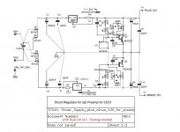
btw, we have played with this version provided below too, so with same PCB mounting modification/thinking it could be also very good (maybe even better) PSU solution 😉
btw, we have played with this version provided below too, so with same PCB mounting modification/thinking it could be also very good (maybe even better) PSU solution 😉
Attachments
You are correct, I test the circuit with non sysmetrical load, that might be the reason why I have imbalance current flow for +ve and -ve trails.. I didnt shorted reference to ground, what I did is use 100 Ohms as dummy load and measure the current, and I got 46 mA and 16 mA respectively. but as Zen said, the circuit should works fine with symetrical load, I believe it might give balance current reading if I equal load both + ve and - ve rail at the same time.. 🙂it will work as planned - with symmetrical load
You are correct, I test the circuit with non sysmetrical load, that might be the reason why I have imbalance current flow for +ve and -ve trails.. I didnt shorted reference to ground, what I did is use 100 Ohms as dummy load and measure the current, and I got 46 mA and 16 mA respectively. but as Zen said, the circuit should works fine with symetrical load, I believe it might give balance current reading if I equal load both + ve and - ve rail at the same time.. 🙂
Sure, try with symetrical load - 100 Ohm between Plus and Gnd, and 100 Ohm between Gnd and Minus at the same time, and check voltages over both 100 Ohms 🙂
do you think this buffer will sound better than the JFET one ? The SK170B /SJ74 is hard to get.. :-(
better ?
certainly not .
worse ? - not much , if you are careful with PSU quality
in low level stages - PSU is 100% of entire story
( fact that active electronics - is another 100% half , is irrelevant in this moment )
certainly not .
worse ? - not much , if you are careful with PSU quality
in low level stages - PSU is 100% of entire story
( fact that active electronics - is another 100% half , is irrelevant in this moment
)Pass B1 does not use j74. It uses a pair of selected Idss sk170.do you think this buffer will sound better than the JFET one ? The SK170B /SJ74 is hard to get.. :-(
These are available in 2sk from this Forum and in Lsk from Linear and the Forum.
Oh my God ! I still struggling to get the split power supply to work. it did not pump out +/-12V but +12.4V and -3.4V when connected to buffer.but it will pump out +12.4V and -12.3V without load.I confused.my conection is intact.Does anyone face the same problem as I do ? SOS plsssss
- Home
- Source & Line
- Analog Line Level
- Poor Serbian Man Optical Volume Control