then just replace all small BC bjts
easiest way ;
check each LDR's LED with diode test on your DMM
I hope you didn't burn any
easiest way ;
check each LDR's LED with diode test on your DMM
I hope you didn't burn any
Hello friends:
I read again the cookbook and after replaced ZD3 and R2 for a potentiometer and get then 15V, jumping R2 the intensity remained high (is a botched job that I hope to resolve more later). I´d like put measures in schematics but I don´t know do it.
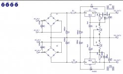
The resulting measures take alls to gnd with jmp 01 and 02 open and main potentiometer at twelve o´clock, are:
Output transformers: 22,62V
PSU rail 15V
Top of the LED1, 4,11V
Between LED1 and VR1: 2,33V
VR1
Leg 1 = 0V
Leg 2 = 2,33V
Leg 3 = 0V
Bottom of jumper 01: 5,75V
Bottom of jumper 02: 1,41V
Top of jumper 01 (from LDR): 13,5V
Top of jumper 02 (from LDR): 14,1V
Between R5 and Q4: 4,1V SUSPECT!
Between R6 and Q5: 2,14v
Current acroos jumper 01 0mA
Current across jumper 02 25mA DANGEROUS!
At this time don´t replaced any parts, I think is better the experts look first.
Any suggestion besides replace the bcs?
I read again the cookbook and after replaced ZD3 and R2 for a potentiometer and get then 15V, jumping R2 the intensity remained high (is a botched job that I hope to resolve more later). I´d like put measures in schematics but I don´t know do it.
The resulting measures take alls to gnd with jmp 01 and 02 open and main potentiometer at twelve o´clock, are:
Output transformers: 22,62V
PSU rail 15V
Top of the LED1, 4,11V
Between LED1 and VR1: 2,33V
VR1
Leg 1 = 0V
Leg 2 = 2,33V
Leg 3 = 0V
Bottom of jumper 01: 5,75V
Bottom of jumper 02: 1,41V
Top of jumper 01 (from LDR): 13,5V
Top of jumper 02 (from LDR): 14,1V
Between R5 and Q4: 4,1V SUSPECT!
Between R6 and Q5: 2,14v
Current acroos jumper 01 0mA
Current across jumper 02 25mA DANGEROUS!
At this time don´t replaced any parts, I think is better the experts look first.
Any suggestion besides replace the bcs?
Finally I chose another pcb that I had at home and I started again carefully.
I detected two mistake choosen parts in the old.
The new PCB works great, but I struggled to match the channels. I'll go to a friend's house with scope when I get appropriate 2M2 potentiometers.
The important thing is that the sound is really good. Now it's time to test LS buffer, buffer-LS-buffer and find my favorite. Then I´d like put remote control, another battle.
Thanks to SP and ZM. The work is really fantastic.
Best regards
P.d:
One LDR have the dot in the other side.
......
One LDR have the dot in the other side.
bummer

PS - sorry , I didn't got that post from 2-nd december
Hi Jose. Enjoy !
You don't need 2M2 potenciometers...
See
http://www.diyaudio.com/forums/diyaudio-com-articles/168796-poor-serbian-mans-optical-attenuator.html
especialy below part that explain this picture:
http://www.diyaudio.com/forums/images/articles/opticalattenuator/original/18.jpg
You don't need 2M2 potenciometers...
See
http://www.diyaudio.com/forums/diyaudio-com-articles/168796-poor-serbian-mans-optical-attenuator.html
especialy below part that explain this picture:
http://www.diyaudio.com/forums/images/articles/opticalattenuator/original/18.jpg
Last edited:
PS - sorry , I didn't got that post from 2-nd december[/QUOTE]
Do not worry, you work a lot for the DIYer for to have to apologizing, and then, reading my English.
Do not worry, you work a lot for the DIYer for to have to apologizing, and then, reading my English.
Buffer PSU
¡Happy new year!
I´d like built in my own board (matrix dots) this PSU for a headphone amp but I´d like too can adjust the voltage between +/- 9 V to +/- 15 V or so. for test sound. ¿Can I put trimers in any place of circuit? This way is very confortable.
Thanks a lot.
¡Happy new year!
I´d like built in my own board (matrix dots) this PSU for a headphone amp but I´d like too can adjust the voltage between +/- 9 V to +/- 15 V or so. for test sound. ¿Can I put trimers in any place of circuit? This way is very confortable.
Thanks a lot.
Jose
HNY to you 😉
which PSU ? shunt , for buffer stage ?
you need to tell me which headphone amps schm , so I can make needed changes , that circuit suit your needs
HNY to you 😉
which PSU ? shunt , for buffer stage ?
you need to tell me which headphone amps schm , so I can make needed changes , that circuit suit your needs
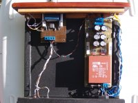
you made proper bipolar supply , as I can see from pics ?
so - 2x18Vac/6VA xformer , and you need 2x9Vdc up to ......... we'll see what max can be
tomorrow , please 😉
so - 2x18Vac/6VA xformer , and you need 2x9Vdc up to ......... we'll see what max can be
tomorrow , please 😉
Hi, does anyone maybe have some matched LDRs (NSL-32SR3) that are for sale? I'd like to buy two pairs if that is enough for unbalanced version of Zen Mod's volume control.
Thanks.
Thanks.
It's udailey, but check this statement from him http://www.diyaudio.com/forums/grou...mfortable-passive-pre-amp-51.html#post3629586 .Uriahp or Uriah Heep?
- Home
- Source & Line
- Analog Line Level
- Poor Serbian Man Optical Volume Control