Zombie thread query!
I got one of these from a friend who built it years back.
I am setting it up - but I don't seem to have the correct current. Vcc is 16v, I measured 0.9v across R1 which means it's drawing about 50mA. I have 14-16v across the top of the ldr strings. But when I put the ammeter across the jumpers I can only get to 7/8mA before the pot reaches the end of adjustment. All seems to match the build, and the ldr works. I think the pot I have is log as all the adjustment is at the very end, but I also notice that the volume is slow to react - eg if I set it half way, maybe 10-15secs later the loudness builds.
Any ideas?
good that I got e-mail about this Zombie move 🙂
frankly, need to wrap my head around a little , to refresh my memory of circuit itself and will reply what I have, tomorrow evening
if I forget, feel free to remind me
what I can say in this moment - you really need to have linear pot
frankly, need to wrap my head around a little , to refresh my memory of circuit itself and will reply what I have, tomorrow evening
if I forget, feel free to remind me
what I can say in this moment - you really need to have linear pot
Last edited:
OK, well I went through every bit of scrap in the workshop here, and no 10k linear pots grr. Asked a friend who has a small business supplying arduino builders etc - but he only had single gang pots. So I'll order one and hopefully get it early next week.
In the meantime, I went back and checked every component on the board and all check out OK. All resistors at the right value, I didn't pull the transistors but given that the unit works then they must also be working. so maybe all that is wrong here is that the pot is logarithmic rather than linear? That would mean that the current only gets moving towards the end of the pot travel, and that is what I am seeing.
The only bit that is still wrong is that the current is too low when I measure across the jumpers.
Fran
Another thought on this today. This build is stereo unbalanced, so uses 2 pairs of LDRs. In that case, I would expect to measure half of the ~15mA current that is specified in the cookbook - the 15mA is for running 4 LDRs?
all "series" LDRs are having their LED parts connected in series
all "shunt" LDRs are having their LED parts connected in series
so, it's irrelevant - current wise, have you 2 of them, or 4 in series - current stays the same
(if you're using 4 + 4 , for ballanced - you populate all LDRs positions; if you use 2+2 (for SE) , you populate appropriate positions, putting jumpers in place of non-populated LDRs)
current - it needs to be set with P1 and P2 trimpots, respectively , on opposite ends of Vol pot rotation
OK, I'm clutching at straws!
So I can only get maximum of ~7mA at either end - and although the pot is log rather than linear, that "should" only mean that it is very sensitive in a narrow range?
So I can only get maximum of ~7mA at either end - and although the pot is log rather than linear, that "should" only mean that it is very sensitive in a narrow range?
is there anything else, not in compliance with text on page 9 and 10 of Cookbook?
ref voltages are OK?
ref voltages are OK?
No all else seems in order
Middle pin of Q3 is 2.47V, VCC is 16V (using a 15V non-CT transformer, so I have 4 diodes in place). Everything else is OK from pages 9&10 except I cannot get the current up to 15mA measured across either Jumper 1 or 2.
It all seems to work just fine other than this. Unless you can see something tha jumps out at you, then I think I will wait a few days for the linear pot to arrive from Farnell, I'll put that in and look again.
Something else I just thought of now as well - these LDRs are very temperature sensitive aren't they? Its bloody cold in the workshop at present, maybe I should bring the build inside and test inside at normal indoor temps.
when you get linear pot, you'll tell me what span of DC voltages you're getting at bases of two CCS BC517 transistors, ref. to GND
OK, I couldn't leave it alone without seeing if it was temperature - its down at about 4 or 5degC in the workshop. I brought the preamp inside, and an hour later, that 7mA reading is now 12.5mA. Range of voltage at the base of Q1 and Q2 is 0.7V to 1.4V
This is looking like it was just temperature related?
This is looking like it was just temperature related?
frankly, eons ago when it was made, I never tried it near zero temp ...... nor it came to my mind that it can be so temp. sensitive
I mean, it isn't logical
when you get proper pot, we'll check potentials at Q1,2 bases again and we'll know more
I mean, it isn't logical
when you get proper pot, we'll check potentials at Q1,2 bases again and we'll know more
Years ago I messed about with LDRs - this was just after Georgehifi had started working with them, but before the better CCS versions and arduino controllers had appeared. I remembered matching some and seeing fairly significant temperature drift in them while measuring.... I think that is what brought the temp thing back into my mind. I think this was reported at the time when people were matching them but haven't searched yet for that info. I'll report back in a few days when the pot lands, but I'm much more reassured now.
I stlll have a bag of 50 or so knocking around here somewhere!
I stlll have a bag of 50 or so knocking around here somewhere!
I did lost interest in those (frankly, being pushed in project by friends) because I realized that sole proper way of doing it is involving everything ppl actually made later - initial calibrating process (best at each power on), only possible with logic control etc.
complexity in which I wasn't interested at all, even ignoring question was I able to do it
anyway, what you have in hands is still decent, under condition that you have some luck with LDR choice .....
time lead me to different volume control approach....... which I'm not likely going to change, ever
I appreciate the idea of simple as possible - out of curiosity - what method for volume control did you adopt?
Ok, I had a look at the iron pumpkin! That's quite the piece of kit!
So the 10k linear pot arrived, easier to use for sure. The voltage on the bases of Q1 and 2 are pretty much the same, varying from 0.7V to 1.4V. Temperature definitely affects the total current though, I did an experiment where I left it in the workshop at 4deg c and current was 8mA per string. Inside in the house at 19dec C and current was 13mA without any other adjustments made.
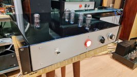
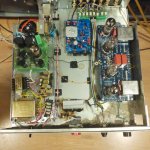
It works great, sounds great, I'm a happy camper.
I've attached a few pics of the build - an old twisted pear relay source selector, into psmls, then to a tube rectified 6sn7 aikido. It sounds very good.
Thanks for all the help (assuming that you don't see anything wrong in the readings above)
Fran
So the 10k linear pot arrived, easier to use for sure. The voltage on the bases of Q1 and 2 are pretty much the same, varying from 0.7V to 1.4V. Temperature definitely affects the total current though, I did an experiment where I left it in the workshop at 4deg c and current was 8mA per string. Inside in the house at 19dec C and current was 13mA without any other adjustments made.
It works great, sounds great, I'm a happy camper.
I've attached a few pics of the build - an old twisted pear relay source selector, into psmls, then to a tube rectified 6sn7 aikido. It sounds very good.
Thanks for all the help (assuming that you don't see anything wrong in the readings above)
Fran
Attachments
just chill
besides fact that I have nothing to object, most important is that your foot is tapping
🙂
besides fact that I have nothing to object, most important is that your foot is tapping
🙂
@Zen Mod It has been many years since this thread started. I am looking for really really excellent volume attenuator or controller. Is this optical volume controller right now still the best one to get or should I look for something else like MUSES 72323, TDK pot, or ...?
Instead of NSL-32SR2 or NSL-32SR3 some use cpc1017n for this. What would be the difference and which one would be better for the sound?
What opinions others have? Anybody have LDR-s, pcb-s or gerbers to share?
Instead of NSL-32SR2 or NSL-32SR3 some use cpc1017n for this. What would be the difference and which one would be better for the sound?
What opinions others have? Anybody have LDR-s, pcb-s or gerbers to share?
- Home
- Source & Line
- Analog Line Level
- Poor Serbian Man Optical Volume Control