Flexible Harness
The flexible harness are like any other flat cable/connector connection. They are usually soldered at one end and inserted into a connector at the other. Just pull out gently of the connector and they come appart. If you cannot move it, it is soldered!
Note: These flex cable connections are not designed to be removed often. Try to reduce the number of time you touch them, the less, the better. Don't get nervous thought, you can easily disconnect them 10 times or more without problem. Be very carefull when you put them back.
I dissassemble the supply, then the audio PCB. Then I disconnect the front Panel from the digital PCB and remove it. Finally, I let the transport and the digital PCB connected together and I remove both at the same time.
Power Supply
I used your parts list as a guide line. No I didn't change the diodes in the supply. This a switching supply and from my experience, the choice of diode in some part of the circuit can be critical. Without the original diode part number and specs, it can be adventurous to replace diode. The circuit can be easily degraded.
No I didn't ground the foil. In two of my good players, there is often foil on top of caps and IC (my Copland CD for example). So I did the same just in case...
Hey guys, I have a question...
I would like to get a similar device and tweak the heck out of it. I mean the best I can.
So since I am tweaking it and all the stuff, would it be possible to add some digital SP/DIF input to the player? This way I would be able to use all the goodies inside(DAC mainly).
I know it sounds like crazy, but is it possible at all? If so, how big a deal is it to implement it actually?

I removed all relays, muting, etc,and basically DC'd, and zero ohm'd the output of my 563 with no problems whatsoever. I like playing with fire. I run my amps wth so much current and uf that if the thing goes into meltdown, the relay in the basement is the fuse at 20A..and the amp will still run 30 seconds after that, no matter WHAT has blown up,shorted, etc. I have had to run to disconnect speaker cables before.... disconnetcting them is my only fuse method.
Needless to say, I never leave the thing on while stepping out. Sounds good though.....
Needless to say, I never leave the thing on while stepping out. Sounds good though.....
Novel Fusing Method
Hey KBK,
Sounds neat. Care to jot down a schematic of how you configured the system so we too could experimet.
I personally turn off my system by pulling out the tubes from my power amps. It's amazing how many burning kleenex I've had to stamp out under foot, but that's a small price to pay.
No AC switches on my gear. That would ruin the continuity of the electrons as they flow through the ether of the silver oxide in the cable.
You know the old saying attributed to Confucius (Kung-fu-tse).
To fuse is to confuse.
Cheers.
Guys,
I read the thread and found something writing 565A is almost the same of 563 model.
I'm going to buy a 565A, so I was wondering if someone could tell me for sure if 565A and 563 are the same player.
thanks!
I read the thread and found something writing 565A is almost the same of 563 model.
I'm going to buy a 565A, so I was wondering if someone could tell me for sure if 565A and 563 are the same player.
thanks!
Hi All,
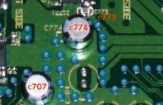
Just got myself a Pioneer DV667A (OZ/NZ version of DV563). After 3 days of running in the player sound details but the brightness and glare around the high is driving me banana. After some searching I am glad to find this post. Reading Vinnie mod list I found that the C773 in my player not what I expected - see attached picture. Just wonder if you all actually replace this with a Panasonic cap or DV667A is not 100% identical to 563. Will appreciate if someone can send me a soft copy of the 563 service manual so that I can check the component list of 563 vs my 667 - just to make sure before I start the mod.
Also, other than KDK replacing the 27Mhz crystal with his proprietary clock, anyone replace theirs?
TIA,
Sam
Attachments

An Updat- DV563 in new clothes
Hi all,
This thread has been quiet for a while.
I thought I would update you on my further adventures.
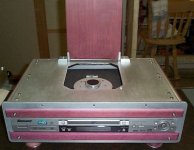
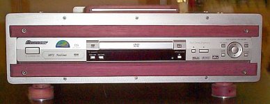
I bought a new Pioneer unit and started to redo it from scratch.
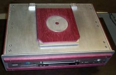
It has a new chassis made of 1/4 inch alluminum plate and it is accented with purple heart wood.
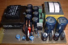
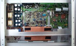
It is a top loader, with 3 new transformers and double regulated 3.3v, 5v and 12v supplies. It has also a new output board sporting OPA 604 single chips which are buffered with a FET and Lt1010 output buffer. This board also has its indepentdent supply, regulated down from +18/-18v and then regulated again using Sulzer style regulators to +14/-14 volts.
Most of this I have outlined on this thread before, so you can get the details there.
I made some further changes to the stock boards.
I replaced all electrolytic capacitors on the "analog" board with Panasonic FC types. The values are described in the earlier posts. The values of the other caps are 50 to 100% higher than stock.
I bypassed each electrolytic on the "digital" board with an equal value Panasonic. The swithcing power supply is modified as before, but is now contained in a covered copper box. The large digital chips have been shielded with copper foil which is grounded to the ground plane.
All new supplies are also fed from a balance capacitor, balanced choke and capacitor filter. The new supplies are meant to be left on always.
I'll post some pictures.
N.
Hi all,
This thread has been quiet for a while.
I thought I would update you on my further adventures.
I bought a new Pioneer unit and started to redo it from scratch.
It has a new chassis made of 1/4 inch alluminum plate and it is accented with purple heart wood.
It is a top loader, with 3 new transformers and double regulated 3.3v, 5v and 12v supplies. It has also a new output board sporting OPA 604 single chips which are buffered with a FET and Lt1010 output buffer. This board also has its indepentdent supply, regulated down from +18/-18v and then regulated again using Sulzer style regulators to +14/-14 volts.
Most of this I have outlined on this thread before, so you can get the details there.
I made some further changes to the stock boards.
I replaced all electrolytic capacitors on the "analog" board with Panasonic FC types. The values are described in the earlier posts. The values of the other caps are 50 to 100% higher than stock.
I bypassed each electrolytic on the "digital" board with an equal value Panasonic. The swithcing power supply is modified as before, but is now contained in a covered copper box. The large digital chips have been shielded with copper foil which is grounded to the ground plane.
All new supplies are also fed from a balance capacitor, balanced choke and capacitor filter. The new supplies are meant to be left on always.
I'll post some pictures.
N.
Just got a DV667A ( same as 563A).
Hi Guys,
Can Vinnie or Larry or someone else please give me the circuit diagram . Especially the DAC and the output stage.
Thanks in advance.
Ashok.
ashokm(at)sify.com
Hi Guys,
Can Vinnie or Larry or someone else please give me the circuit diagram . Especially the DAC and the output stage.
Thanks in advance.
Ashok.
ashokm(at)sify.com
Pioneer schematics
Hello Ashok,
I tried to email you the schematics, but your preferences state that you do not want to receive email through this board.
So, how are we supposed to send you what you request?
N
Hello Ashok,
I tried to email you the schematics, but your preferences state that you do not want to receive email through this board.
So, how are we supposed to send you what you request?
N
Email activation
Hi Nic,
I don't know why my email through the forum does not work. I tried to set it right several times and it stays locked . I'll try again.
In the meantime I did give you my email ID in the earlier post. Just replace the (at) with @ .
ashokm(at)sify.com
Sorry for all the bother.
Thanks for your effort.
Ashok.
I fixed the email button. Can't figure out why it didn't work earlier !
- Status
- Not open for further replies.
- Home
- Source & Line
- Digital Source
- Poogeing the SACD: The Pioneer 563A