Hi Bostjan !
Its good to see someone from the neighborhood !
Dont worry about those red plates, just increase the number of windings, it will help. Myself and Ivan had a lot of experimenting with turns number, we believe that 15 turns are far from ideal in this setup (EL/PL 519 , 600 Volts).
We even tried Litz wire from an old radio, but ended up with NO flame and RED plate, consider this a dead end.
BTW, did anyone use bigger tube for the oscillator ?
Hi Lord Winter,
nice to hear also.
thanks for info.
How many windings you suggest?
Bigger tube - you think about 813 tube?
regards, Bostjan
nice to hear also.
thanks for info.
How many windings you suggest?
Bigger tube - you think about 813 tube?
regards, Bostjan
Hi Bostjan !
Try doubling the number, or perhaps more, but the spacing should remain the same. A thicker, silver plated wire is a must for maximum efficiency.
The 813 would be a nice candidate for an overkill plasma tweeter, but it needs 1,5kV++ for full effect. I even considered GU-81, but that would be a really hazardous toy to play with.
Recently I bought a pair of OS51 tubes (Pa=45W) that should give considerably more power than PL519, when running from 900V B+. Right now my hands are full, so I will post the results later...
Hi Lord Winter,
thank you again.
Wire should be same 0.9mm?
I have some pure silver wire 1mm.
I am very interested of your progress with big tubes for plasma tweeter.
It would be nice to see some photos.
One question:
did anyone tried plasma tweeter with ignition coils? Like here:
http://www.barlowlabs.upgradecolumb...ker.pdf#search="plasma speaker ignition coil"
regards, Bostjan
Hi there !
The wire does not have to be solid silver, that's a waste, just silver enameled wire("skin losses"). At higher frequencies only the outermost layer of wire is conducting, therefore we need greater surface. Thin, enameled copper ribbon would be ideal, but that is almost impossible to wind on a coil former.
I bought the materials in Budapest, Hungary.
A company called "HAM bazaar" is selling surplus military and radio-amateur stuff at really competitive prices (OS51 for less than 10 EUR, 40x90 mm ceramic coil former for 0,4 EUR ...)
Attachments

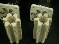
Lord Winter this is very nice tubes and ceramic.
I made litlle search for tubes, but i didnt find it.javascript:smilie(' ')
')
smash
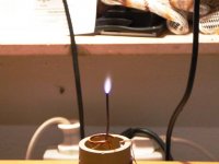
Yesterday i tried with double windings and working much better.
bigger flame and tube is not getting redjavascript:smilie('🙂')
smile
But i got other problems. It makes computer to confuser, cd player is not working properly, when is plasma tweeter working.
I guess i have now to make metal case and ground it.
I am very interested for your progress with plasma tweeter.
best regards, Bostjan
I made litlle search for tubes, but i didnt find it.javascript:smilie('
')smash
Yesterday i tried with double windings and working much better.
bigger flame and tube is not getting redjavascript:smilie('🙂')
smile
But i got other problems. It makes computer to confuser, cd player is not working properly, when is plasma tweeter working.
I guess i have now to make metal case and ground it.
I am very interested for your progress with plasma tweeter.
best regards, Bostjan
Attachments
Well done Bostjan !!!
You will never find almost any data regarding the OS51, but actually it is an exact copy of PE 1/100 - datasheet available.
RF shielding is mandatory !
A year ago me and Ivan made a "test run" with our plasma. I made a mistake by leaning closer to the coil (about 40cm). After a half minute I realized that the sound is changing a bit, it became less "harsh". A few moments passed and suddenly my vision began to blur, I felt dizzy and almost vomited. Needless to say, we shut down the plasma very fast.
It took about half hour to return to normal state, still feeling some headache, so be cautious with this toy !
We used a perforated metal cage from an old TV.
However I know a simple cure for this problem, it might help.
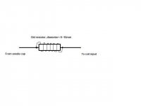
All you need is to put a "harmonic supressor" between the anode and the coil. Just take an old 50-220 Ohm / 2-3W resistor and wind a few turns of 1mm copper wire on it (6-10 turns will do). Solder the wire ends on the resistor leads and youre done !
I cannot guarantee the succes, but it will help to minimize the interference in the lower TV band.
You will never find almost any data regarding the OS51, but actually it is an exact copy of PE 1/100 - datasheet available.
RF shielding is mandatory !
A year ago me and Ivan made a "test run" with our plasma. I made a mistake by leaning closer to the coil (about 40cm). After a half minute I realized that the sound is changing a bit, it became less "harsh". A few moments passed and suddenly my vision began to blur, I felt dizzy and almost vomited. Needless to say, we shut down the plasma very fast.
It took about half hour to return to normal state, still feeling some headache, so be cautious with this toy !
We used a perforated metal cage from an old TV.
However I know a simple cure for this problem, it might help.
All you need is to put a "harmonic supressor" between the anode and the coil. Just take an old 50-220 Ohm / 2-3W resistor and wind a few turns of 1mm copper wire on it (6-10 turns will do). Solder the wire ends on the resistor leads and youre done !
I cannot guarantee the succes, but it will help to minimize the interference in the lower TV band.
Attachments
It's likely not the RF (which has never been proven to have an effect on biological tissue, unless you have sufficient power to actually heat it), but the ozone and nitrogen dioxide.
Of course, why bother with RF and tesla coils? Just use DC.
Of course, why bother with RF and tesla coils? Just use DC.
Nixie said:It's likely not the RF (which has never been proven to have an effect on biological tissue, unless you have sufficient power to actually heat it), but the ozone and nitrogen dioxide.
Of course, why bother with RF and tesla coils? Just use DC.
Hi Nixie,
what do you mean Just use DC? Well i opened for other idea.
to use ignition coils?
Yes i believe that plasma tweeter is quite danger.
I had plan to put in well RF protected case with alu horn. Ozone is disapearing with heat.
regards, Bostjan
I mean, a plain linear power supply to create high voltage DC for the discharge, then modulate it with audio. For example, I took a 2 kVA industrial control transformer I got on eBay for $30, and rewound the secondaries for 2500 VAC. Rectified and with a CLCRC filtering, I get 2850 VDC with ripple on the fraction of millivolt.
Nixie said:I mean, a plain linear power supply to create high voltage DC for the discharge, then modulate it with audio. For example, I took a 2 kVA industrial control transformer I got on eBay for $30, and rewound the secondaries for 2500 VAC. Rectified and with a CLCRC filtering, I get 2850 VDC with ripple on the fraction of millivolt.
Do you have schematic for that?
regards, Bostjan
You guys cant be serious !
The basic advantage of the oscillator-tesla coil design is to have a very STABLE discharge at LOW power levels.
The DC arc tends to be rather problematic:
- great variations of current consumption, depending on electrode distance, ion and humidity levels of air.
- one of the electrodes will start to wear off quickly, you will have to readjust the distance from time to time = constatnt babysitting
- the actual device will consume enormous amount of energy
- modulation can be an issue at these power levels
I advise you to reconsider the whole idea, however its worth trying.
A year ago I made small but powerful solid-state tesla coil for a friend. We experimented and learned a lot about high voltage AC discharges. Our small "scientific" team abused almost anything we could lay our hands on, from wood to plexiglass, including CDs (its rather spectacular) and live cockroaches(indicates that my friend is clearly insane).
My point is, that its worth to experiment and gain practical knowledge, no matter how crazy/pointless subject you're working on.
There are so many things wrong with your post, I don't know where to start.Lord Winter said:You guys cant be serious !
Who's talking about an arc? Arc is indeed crap, but so is the corona discharge of a tesla coil. Does the image below look like an arc to you?The DC arc tends to be rather problematic:
An externally hosted image should be here but it was not working when we last tested it.
The basic advantage of the oscillator-tesla coil design is to have a very STABLE discharge at LOW power levels.
Low power levels is a bad thing. The plasma is more linear if its average temperature is very high compared to the audio frequency modulation. Mathematical derivation of this result is given in Hill's patent on plasma speakers, US #4,219,705. Of course, I've only referenced this like 50 times throughout the forums here. He also talks about why corona discharge is not as good as a glow discharge. You only had to go back to post #53 in this thread. But hey, clearly you're not the type of person to actually bother to read a thread before crapping in it!
Blah blah blah... you wasted your time listing problems with something no one here is discussing. Let's see what other strawmen you'll find to attack next!- great variations of current consumption, depending on electrode distance, ion and humidity levels of air.
- one of the electrodes will start to wear off quickly, you will have to readjust the distance from time to time = constatnt babysitting
- the actual device will consume enormous amount of energy
- modulation can be an issue at these power levels
I advise you to consider the measurements shown below for the 500 Hz and above frequency range, and show me one tesla coil corona discharge that can reproduce anything this good with a crossover this low, at reasonable SPL.I advise you to reconsider the whole idea, however its worth trying.
An externally hosted image should be here but it was not working when we last tested it.
An externally hosted image should be here but it was not working when we last tested it.
An externally hosted image should be here but it was not working when we last tested it.
Before you post next time, I suggest you study a good text discussing the various types of discharges through the whole range: dark, corona, subnormal glow, normal glow, abnormal glow, arc, thermal arc. I've posted at least the I-V curves for these multiple times throughout the forums.
[Note:] Images courtesy of Jay Philippbar.
WOW that are some very nice plots! the step response is practically the same as it would be in theory!
Okay Nixie, don't get it too serious.
My intent was to help Bostjan setting up his project, for the benefit of others, too.
Unfortunately, most of us cannot afford the equipment you're working with. Sorry, I'm just trying to be practical.
Your reaction was over-emphasized.😡
My intent was to help Bostjan setting up his project, for the benefit of others, too.
Unfortunately, most of us cannot afford the equipment you're working with. Sorry, I'm just trying to be practical.
Your reaction was over-emphasized.😡
Afford? LOL. An appropriate power supply can be built for below two hundred dollars with used parts from eBay.
Nixie, do you have a link to your posts about glow discharge ?
I searched the forum , but could not find too much.
Do you use gas or metal catalysts ?
I searched the forum , but could not find too much.
Do you use gas or metal catalysts ?
- Home
- Loudspeakers
- Planars & Exotics
- plasma tweeter