No more than a typical class A amplifier to produce the same SPL through medium efficiency speakers.
I may be incorrect, but I seem to recall that the Hill Plasmatronics used a quartet of 572B tubes (triodes), rather than sweep tubes (pentodes/tetrodes)...
Nixie, are you ever going to post any pics of your experimental work on your "designs"?? It would certainly help to give your posts a greater degree of credibility, fwiw.
Bernhard, very clean implementation! 😀
DIYers, note the perf metal (grounded/shielded) enclosure around the electronics?
_-_-bear
Nope, they are TV pentodes. Jay sent me a schematic of the final stage in the Plasmatronics, and they are pentodes. Using triodes for current drive makes no sense (the discharge drops a constant voltage so it's not possible to have voltage drive). As for it being a "quartet" of tubes, once again you embarass yourself. Did you not notice in the photograph in post #95 in this thread there are FIVE cathodes? Oh wait, I just remembered, people around here tend to post in threads they don't actually read...
As for questioning my credibility, well, I think you know where you can put that attitude of yours. I'll take photos as soon as you buy me a digital camera. However, I'm not quite clear what images will demonstrate, as in recent years MHCD have been well researched and there is a well established literature (which I've cited, as you'd have noticed if you weren't too lazy to use the forum search).
As for questioning my credibility, well, I think you know where you can put that attitude of yours. I'll take photos as soon as you buy me a digital camera. However, I'm not quite clear what images will demonstrate, as in recent years MHCD have been well researched and there is a well established literature (which I've cited, as you'd have noticed if you weren't too lazy to use the forum search).
Dear Nixie,
You cited some rather esoteric Journal articles... I have no idea what they say or do not say and I rather doubt that many others do either. It's entirely unclear that there is direct application to audio based on what you have writen so far. There well may be... unclear.
Then you go on to cite some personal experiments that you seem to have claimed validate the principle, yes?
Ok...?
As far as a digital camera? Do you have a computer, access to a computer with a scanner? Take a regular photo and scan it? Take the photo to a friends house with a scanner? Borrow a friends digital camera? Have a friend come over and take a pic? Buy a cheezy <$20 digital camera from a "big box" store. I saw some at an Ekerd drug store a few days ago... including brands like "Polaroid" stamped on them... they're like 1.3Mpixels, which is good enough!
Worst case, take a regular photo, mail it to me I'll scan it and post it for you??
Ok...?
Now, I have seen the Hill Plasmatronic Speakers on several occasions... while they may have been sweep tubes (and I am skeptical of that, my memory says they were too large for sweep tubes), I do not recall seeing 5. Seems to me they were set up in a P-P sort of configuration... and it's been a while since I saw the patent, might even have it on this machine, but I really really think that if there were 5 VACUUM TUBES in it, I'd have noticed that odd number... although you seem to be saying that there is one tube per "cathode" that feeds the helium??
Now, look, Nixie you may be correct in all this, which is fine, but try to keep yourself under control here, this is just a discussion about audio and audio ideas... any and all claims can and will be questioned. If you have the "goods" and the facts, there is no need to become emotional or defensive if questioned.
In addition, your posts have the tone, if not the intent of being despositive and didactic - meaning you speak as if you are an expert - which is fine, I'm more than happy to learn new things. So, if you want to present yourself in that light, be prepared to field all manner of questions on a wide range of subjects - especially the ones that you brought up in the first place! ok?
_-_-bear
Once again, the discharge is constant voltage! You cannot have voltage drive for it, it's current drive, and triodes are not used for that. Read the patent, read information on discharges. I've done plenty by providing references, and am not your library!
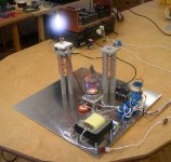
As for photos, I posted my power supply and initial discharges two years ago with a borrowed camera:
http://www.diyaudio.com/forums/showthread.php?postid=469140#post469140
If you look at the page source, you'll notice the image links. They are missing now since I had to clear out the stuff I was hosing on the university server, but it's clear from the discussion following that post that those images were there and people saw them. Once again, I wouldn't have to explain all this if you had bothered to do a bit of forum search.
As for "esoteric Journal articles"... you should be ashamed of your incredible arrogance in calling papers esoteric just because you haven't heard of them. You think the IEEE and the Journal of Applied Physics are esoteric organisation? I'm at a loss for words here...
There are hundreds of papers published on microhollow cathode discharges -- which you'd know if only you had... yep, you guessed what I'm about to say for the nth time... done a little bit of search!!
Yo Nixie -
I have read a whole lot of your posts.
Including the ones as Prune.
Need we say more about that?
As far as being a "library"??
Funny.
Not.
If the links to your work are gone, and that was two years ago, and this is now, is that my fault or negligence?
Let me ask you, you don't rate an alumni account??
You no longer have copies of your own work?
And yes I have heard of the Journal of Applied Physics.
That I do not have it handy on my shelf should hardly be unusual.
Are some of the articles available without charge online?
Cite the URLs please.
Illuminate the subject, dear friend.
In addition, most of the articles in such journals - and yes that is an esoteric journal, what do you suppose the typical monthly circulation might be?? who do you think reads it?? - do not concern themselves with anything but research on the leading edge. Which, in case you fail to comprehend, is frequently & usually a long, long way from practical usage, application, or implementation outside a lab.
Now, here we are in a DIY Forum on audio. Not in a forum on applied physics, notwithstanding that physics underlies everything, right? So, for you to say "There are hundreds of papers published on microhollow cathode discharges -- which you'd know if only you had... yep, you guessed what I'm about to say for the nth time... done a little bit of search!!" is pretty darn arrogant and innane, my friend.
So if you have expertise, as I said, share it - and cease acting like an arrogant professor looking down his/her nose.
In that spirit, please explain how you formed your "microhollows" to create your discharge(s)?? Then perhaps we'd actually learn something from you...
_-_-bear
The papers I mentioned discuss experimental results. That's why it said "Applied Physics", for crying out loud! And if you can't access them, I'll grab them again and email you the PDFs.
As for images no longer being available, that's the case with all images I've hosted, which is also apparent from other threads, such as the one showing the project I was most proud of, the internals of my DAC with the motorized attenuator and coaxial-on-non-rotating-volume-knob moving indicator.
How I made the microhollows -- I'm sure I've written that somewhere -- I drilled them. They're not that micro -- 1 mm are sufficient at my power levels (most papers that use round ones have them about 0.5 mm). The tungsten was drilled with a carbide bit, then plated with chloroplatinic acid (made by electrolytically dissolving in HCl a small amount of platinum wire, and addition of a bit of lead acetate which was made by the method discussed on the sciencemadness.org forums). The sapphire wafer (free samples available if you bug the various manufacturers) was drilled under water with jeweller's diamond bits -- slow, but usually a bit will last for three or four holes if you do it under water. The tungsten was cut to size with a regular rotary tool cut-off wheel. The sapphire was cut with same tool using a diamond wheel under water.
The platinum plating wears off quickly. To avoid that the procedure of US patent 4240878 is necessary, whereby the item is baked under vacuum and some diffusion of the plating into the substrate occurs. I can achieve sufficient vacuum with the water aspirator (I have one for my chemistry stuff), but I don't have a furnace that can both hold vacuum and achieve the necessary temperature, so I intend to send my final electrodes to a friend from the sciencemadness forums that has the right equipment. I did try it at somewhat lower temperature that a Pyrex tube I sealed with a propane torch could withstand, but it didn't work very well. It is possible that even the full temperature won't work right, as the patent uses tantalum rather than tungsten as substrate.
My initial electrodes are 0.4 mm width so I can accomodate five in the small semicircle needed to get the right size discharge (about twice that of the Plasmatronics). Unfortunately, despite the platinum plating heat is still an issue, and I cannot heatsink them properly. I intend to make them much longer in the other dimension than the 1 cm I currently use, so I can clamp on proper heatsinking. That may require a second layer of sapphire on top with a larger hole to prevent the upper surface of the MHCD sandwitch from affecting the discharge (i.e. only the MHCDs themselves should serve as electron source).
My main concern is a non-linear I/V characteristic in the operating range (though the papers I referenced do not show that, they are taken as a series of DC measurements); if so, I will have to change the drive arrangement, and possibly need a separate supply for the MHCD biasing as opposed to the simple resistive bias. Additionally, since the MHCD sandwitch has two planar electrodes with a thin semiconductor between them, I don't know if the parasitic capacitance of this would have any effect at audio frequencies.
Current progress -- power supply change to increase power, and some safety things as the supply capacitors store almost 1500 Joules when no load (changed connectors from BNC to SHV as BNC is only rated at 500 V, added vacuum relay to disconnect power supply output if no load is detected since that means the connectors are left unplugged, etc.). Then I'll cut the longer electrodes and send them off for the vacuum baking. Thing I need to figure out how to do -- measure the AC I/V characteristics of the discharge so I can design a proper driver for the thing. At this point I don't know the easiest way to do that, so I'm open to suggestions. It would be nice to have this done by the end of the year, so I can start thinking about amplifier and speakers for the sub-500 Hz band.
Ok!
Now we're talkin!
Quite interesting. But hard to fully visualize.
So, please do send me .pdfs!!
Email me if they are >500kb, I'll give you an addr with big storage... not sure what email addr this account is pegged to.
I have no idea how to measure the I/V in your set up, some sort of series arrangement with a current pick up would seem suitable, or else an inductive arrangement to sense the current... perhaps. If it's not linear, but has a curve, probably you can "pre-distort" the drive before the amplifier, one would hope that there is a fairly linear region... and of course there is always feedback?
Dunno about you, but I back up important things on CDR and an extra hard drive... you might want to start doing that if you have not yet done so??
_-_-bear
PS. fwiw, I think you might be really on to something...
Nixie, maybe a pair of this one ? 900W RF power amp.
http://cgi.ebay.com/ANALOGIC-AN8102...ryZ26237QQssPageNameZWDVWQQrdZ1QQcmdZViewItem
http://cgi.ebay.com/ANALOGIC-AN8102...ryZ26237QQssPageNameZWDVWQQrdZ1QQcmdZViewItem
For what? The whole point of my discussion is DC discharges, not RF. Even if this could be converted to audio frequency, it's probably voltage output, not current. Then there's the "optimized for pulsed service" mentioned...
I already have the output devices, a pair of 250 W tetrodes. Since the discharge dissipates most of the energy, rather than the current sink, these are sufficient for the 900 W per channel my supply puts out.
I already have the output devices, a pair of 250 W tetrodes. Since the discharge dissipates most of the energy, rather than the current sink, these are sufficient for the 900 W per channel my supply puts out.
Here is another projekt with bigger tubes 4/400A:
http://www.emsp.tu-berlin.de/lehre/mixed-signal-baugruppen/plasmalautspr250W
It looks impressive and simple, goes till 300 Hz.
But not shure how much HF does it produce.
regards, Bostjan
http://www.emsp.tu-berlin.de/lehre/mixed-signal-baugruppen/plasmalautspr250W
It looks impressive and simple, goes till 300 Hz.
But not shure how much HF does it produce.
regards, Bostjan
Attachments
a333bt said:
But not shure how much HF does it produce.
250W per channel
Hallelujah.
about distortion problem
Did anyone measured more things.
How about the audio distortion of plasma tweeter.
Did anyone measured more things.
How about the audio distortion of plasma tweeter.
Hello,want to build my own too
Is this rf part correct.See my picture please.
Capacitors are mounts behind the choke coil(no value for the moment)
Is it correct?
At 35 Mhz ,are they necessary?
In mostly schematic they miss.
Thanks for reply.
Is this rf part correct.See my picture please.
Capacitors are mounts behind the choke coil(no value for the moment)
Is it correct?
At 35 Mhz ,are they necessary?
In mostly schematic they miss.
Thanks for reply.
An externally hosted image should be here but it was not working when we last tested it.
I had the acapella tw1 for repair and it was very lame performing for anybody that would use them at more than 90db...
Audio distortion of a plasma tweeter is never published for a reason. I measured 5-10% distortion at 110db@3inch (equal to ~92db at 2Meter listening position)
they do not worth the effort at all IMHO. (very respectfully)
acapella ion TW 1S plasma tweeter measurment and impression
Audio distortion of a plasma tweeter is never published for a reason. I measured 5-10% distortion at 110db@3inch (equal to ~92db at 2Meter listening position)
they do not worth the effort at all IMHO. (very respectfully)
acapella ion TW 1S plasma tweeter measurment and impression
Thanks for your reply and your website Martin.
Want to know why they are so expensive?
Common electronic components in a U-rack for 25000$ a pair.
Want to know why they are so expensive?
Common electronic components in a U-rack for 25000$ a pair.

Hello,
How you designed your horn?Please.
Have you a draw?
Regards
- Home
- Loudspeakers
- Planars & Exotics
- plasma tweeter