Hey guys,
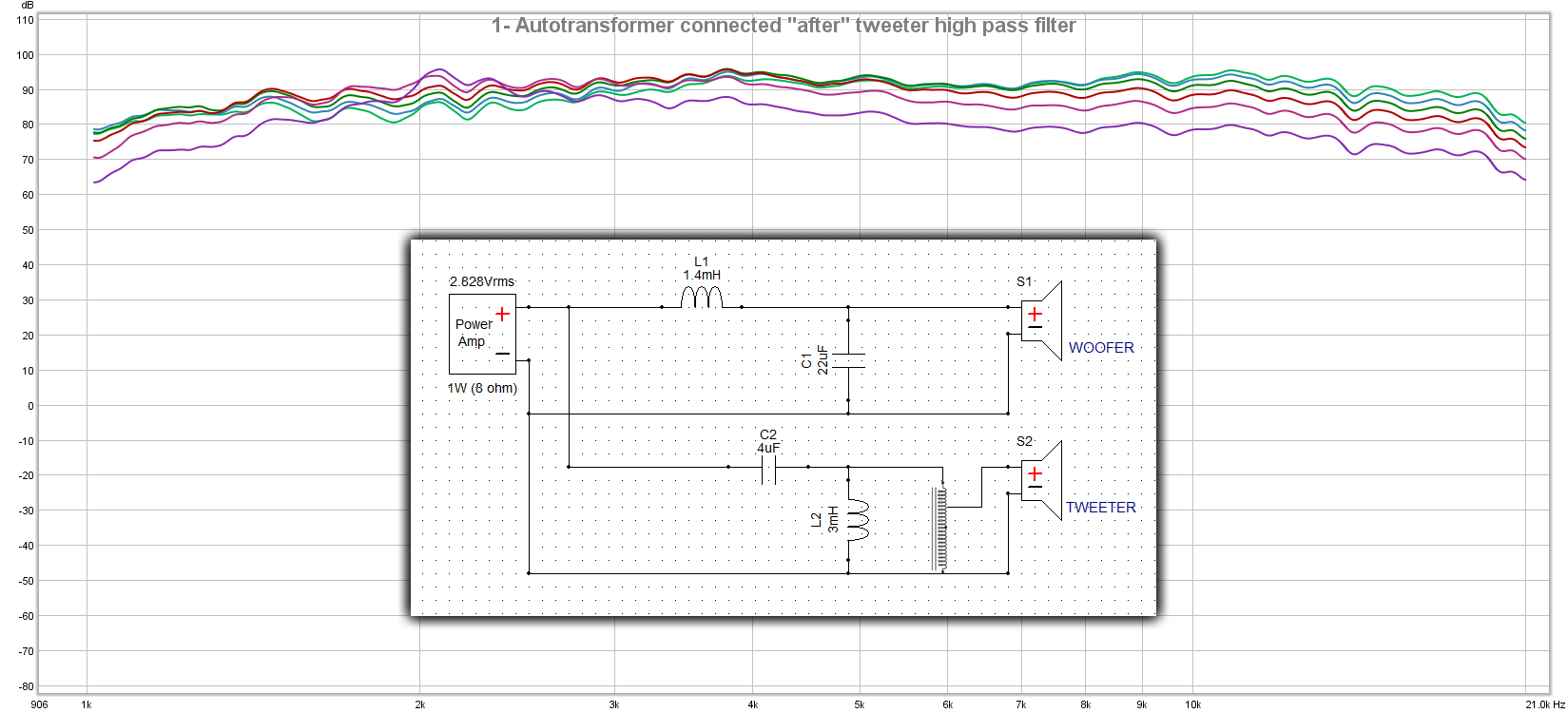
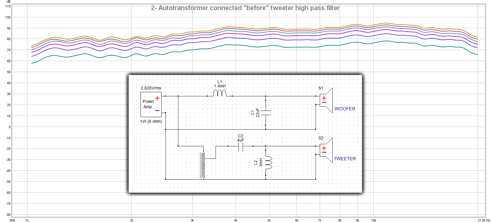
actually I'm building a two way speaker and I wanted to attenuate the tweeter using an old school autotransformer. first of all I located it after tweeter HPF but when I measured all taps frequency response I felt something is wrong. Autotransformer should not change the frequency response like this so I removed it and connected it before the HPF and the frequency response seems correct.
I want someone tip me off where is the right place to connect autotransformer in a XO network and if someone can explain the reason of this frequency response it would be great. (I suppose autotransformer after a LR2 filter would we a second inductor in parallel with the first inductor)
-------------------
Attachments
Last edited:
FWIW here's an ancient Altec two way autoformer schematic: http://digilander.libero.it/steveviso/audiogarage/N800schema.jpg
GM
GM
I am no expert on transformers, but the crossover network (cap and coil) is designed around the assumption you have a very low input impedance and a fixed known output impedance. So if different setting on your autotransformer change the impedance seen by your crossover, it's response will change. That is why you see L-Pads used in crossovers, as an L-Pad is designed to provide a fixed impedance regardless of attenuation setting.
What @olsond3 said. With the autotrafo after the 2nd order filter you'll have varying damping as you change the taps. The resistive component of the tweeter's impedance is providing the damping and this is changing (as presented to the filter) with differing attenuations. Reducing the tweeter output is going to result in too little damping.
The best place to have your autotrafo is before the filter - its being then driven by a low impedance (your amp) and trafos give less distortion in such a circumstance. Its output impedance is going to be lower than the input (ignoring losses) hence more than good enough to drive the LC filter.
The best place to have your autotrafo is before the filter - its being then driven by a low impedance (your amp) and trafos give less distortion in such a circumstance. Its output impedance is going to be lower than the input (ignoring losses) hence more than good enough to drive the LC filter.
Might write pages on it but the short answer is: in principle avoid autotransformers in crossover networks, you are opening a huge can of worms if you try to.
Since you want to *attenuate* , just go the tried and true resistive way.
Since you want to *attenuate* , just go the tried and true resistive way.
Oh, dear!
So little really useful information in this thread so far!
Contrary to what has been said:
- autoformers are possibly the best way to attenuate a tweeter;
- they should be positioned AFTER the high-pass section, to protect them from high-energy low frequencies, which can saturate their core and lead to distortion.
But, also:
- attenuating a tweeter using an autoformer results in a much higher load impedance to the high-pass filter, and one that changes for each different attenuation step;
- THEREFORE, autoformers must be used with a shunt resistor in parallel to their input, and in principle the resistor value must be different for each attenuation step, so that the resulting total load impedance remains the same as the one assumed for the calculation of the high-pass filter.
Having said this, for large attenuation values (i.e., when the tweeter is attenuated more than -10dB, such as is the case when compression drivers are used with direct-radiating woofers), the (autoformer+tweeter) impedance is so high, that in practice a fixed shunt resistor of 8.2 Ohms results in an overall ~constant 8 Ohm load all the way down from -10dB to -20dB or more.
That's all there is to it, really - I hope this clears things up for the OP 🙂
Marco
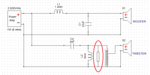
[EDIT] for the OP: I have attached a revised schematic highlighting the resistor that you were missing!
So little really useful information in this thread so far!
Contrary to what has been said:
- autoformers are possibly the best way to attenuate a tweeter;
- they should be positioned AFTER the high-pass section, to protect them from high-energy low frequencies, which can saturate their core and lead to distortion.
But, also:
- attenuating a tweeter using an autoformer results in a much higher load impedance to the high-pass filter, and one that changes for each different attenuation step;
- THEREFORE, autoformers must be used with a shunt resistor in parallel to their input, and in principle the resistor value must be different for each attenuation step, so that the resulting total load impedance remains the same as the one assumed for the calculation of the high-pass filter.
Having said this, for large attenuation values (i.e., when the tweeter is attenuated more than -10dB, such as is the case when compression drivers are used with direct-radiating woofers), the (autoformer+tweeter) impedance is so high, that in practice a fixed shunt resistor of 8.2 Ohms results in an overall ~constant 8 Ohm load all the way down from -10dB to -20dB or more.
That's all there is to it, really - I hope this clears things up for the OP 🙂
Marco
[EDIT] for the OP: I have attached a revised schematic highlighting the resistor that you were missing!
Attachments
Last edited:

I've seen and heard the above scheme used to good effect. But I have to wonder - why not just use two resistors?
Sure, two resistors in an L-pad will do the trick quite nicely, and with minimal fuss.
However, when a lot of attenuation is required (e.g., -22.5dB in my own system), an autoformer-based solution just sounds a little bit better, IMHO: more dynamic, essentially, and possibly subjectively slightly more "refined", for whatever that may be worth.
In any case, I wasn't suggesting that one must use an autoformer, but only pointing out how to use it properly, and explaining why the OP was getting weird results.
Why?
Help me understand this. What known electrical properties of the autoformer make it sound different and what would make those differences better? I assume it can only have more distortion than a resistor divider if undersized (saturation, hysteresis) and some frequency response variations. Resistors could have a tiny amount of inductance, some miniscule variation with heat if undersized, self noise below 100 ohms isn't going to matter.
Sure, two resistors in an L-pad will do the trick quite nicely, and with minimal fuss.
Help me understand this. What known electrical properties of the autoformer make it sound different and what would make those differences better? I assume it can only have more distortion than a resistor divider if undersized (saturation, hysteresis) and some frequency response variations. Resistors could have a tiny amount of inductance, some miniscule variation with heat if undersized, self noise below 100 ohms isn't going to matter.
I don't think it's a matter of the intrinsic characteristics of the autoformer vs. the series resistor, but rather of the interaction of the attenuated tweeter with the driving amplifier.
But as I said, the differences are subtle. Not worth losing sleep over them ;-)
But as I said, the differences are subtle. Not worth losing sleep over them ;-)
marco_gea: You made some claims of clearly audible differences worth understanding: 1) "Best" and 2) " an autoformer-based solution just sounds a little bit better, IMHO: more dynamic, essentially, and possibly subjectively slightly more "refined", for whatever that may be worth."
If it comes down to interaction with the amplifier, I can see that could happen if it presented a higher impedance to the amplifier. Amplifiers typically have lower distortion when used with higher impedance loads (Doug Self). So the transformer when used to attenuate should present a higher impedance, unless you place an 8 ohm resistor at the input to the autotransformer, as suggested, then the load to the amplifier will look identical. I'm not seeing the mechanism for audible improvement using well understood electrical properties.
If it comes down to interaction with the amplifier, I can see that could happen if it presented a higher impedance to the amplifier. Amplifiers typically have lower distortion when used with higher impedance loads (Doug Self). So the transformer when used to attenuate should present a higher impedance, unless you place an 8 ohm resistor at the input to the autotransformer, as suggested, then the load to the amplifier will look identical. I'm not seeing the mechanism for audible improvement using well understood electrical properties.
Send an email to Dave Slagle (Emia audio ) since he can custom wind autoformers / transformers to your specs. Good luck.
Help me understand this. What known electrical properties of the autoformer make it sound different and what would make those differences better?
FWIW: intact audio
GM
If these advantages of an autoformer over a L-pad or a simple resistor in series can be measured or verified otherwise, the explanation might be that the tweeter sees a decreased source impedance from an autoformer, while the impedance usually is increased by resistors. No need to worry about saturation effects in the tweeter section in my opinion, as the signal Level isn't that large here ans a transformer may cope with the HF range much easier.
Best regards!
Best regards!
If the tweeter is 8 ohm and draws no more than 10 watts...
ALK Engineering
Click on Klipsch Loudspeaker Upgrades, then Tweeter Attenuators.
ALK Engineering
Click on Klipsch Loudspeaker Upgrades, then Tweeter Attenuators.
Got it. Higher impedance presented to amplifier.
Thanks for the references. So it looks like the benefit comes from putting it before the crossover so that it can present a higher impedance to the amplifier, resulting in lower amplifier output stage distortion. If I keep reading, one of these days I may actually understand what's going on!
Another source for autoformers is Bob Crites: Autotransformers | Critesspeakers.com
Mast_mutter on the auction website is yet another source
Mast_mutter on the auction website is yet another source
- Home
- Loudspeakers
- Multi-Way
- Placing autotransformer in crossover