Here's a good example of how JBL used to use autoformers ( back in the day ).
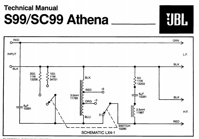
The point is that an autoformer is also an inductor and some of the more clever designers will just build it into the overall network ( when they can ).
Notice the switched conjugate resistors ( source side of the autoformer ) working to present a consistent impedance to the preceeding capacitor.
I'm a bit surprised the OP didn't see the "reflected" impedance issue crop-up since those pics seem to be snaps of XSim ( which has an excellent impedance window ).
🙂
Attachments

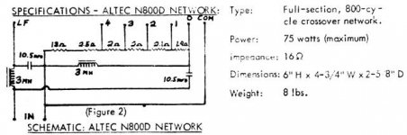
FWIW here's an ancient Altec two way autoformer schematic: http://digilander.libero.it/steveviso/audiogarage/N800schema.jpg
GM
GM
Must be a case of dimming eyes, but that's no autoformer, instead that's Altec's ( clever ) kludge-up in how-to-make a multiple-fixed attenuation LPad ( using resistors ).
Multiple taps on a single Ohmite variable 25W?? wirewound resistor are implemented.
An externally hosted image should be here but it was not working when we last tested it.
Here's a thread ( over at AK ) that details the N800E ( using resistors )..
Worth noting is that the posted schematic is incomplete ( in the posted schematic the HF section wasn't referenced to ground ).
Still, it's good info if one uses it carefully.
The exposed N800E will look something like this;
🙂
Attachments
Last edited:
The original 800D [among others] had an auto-former and that's the correct diagram AFAIK, but I can't find any pre LTV docs on-line, so not surprised that this apparently was yet another example of their extreme cost cutting demands that ultimately destroyed them.
GM
GM
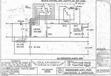
I have a pair of Tannoy Monitor Golds with autotransformers in the crossovers.
The Tannoys have 5 taps
The Tannoys have a single 50 ohm resistor connected to the autotransformer which is switched in the opposing direction to the tweeter.
When the HF is in the highest position the 50 R is disconnected.
I understand what the following parts of the HF circuit do but I am unclear on how the 50R effects the circuit
Copy of schematic attached, the only difference from what I have is the LF inductor is nearer to 3mH.
Attachments
When switched in, the 50 ohm resistor lowers the circuit resistance as seen by the 6.8uF cap.
It doesn't matter if it's placed in front or behind the autoformer > the 50R resistor still lowers the circuit impedance.
🙂
It doesn't matter if it's placed in front or behind the autoformer > the 50R resistor still lowers the circuit impedance.
🙂
These old circuits were designed without computers and simulation software.
When I designed speaker and couldn't attenuate the mid and tweeter because the woofer was so efficient (91 dB), I had a very hard time avoiding electrical resonances and peaks in the response. I couldn't add series resistors to damp resonances, and resistors parallel to the mid and tweeter made the impedance drop too low.
I believe that the best reason for the parallel resistors in the autoformer networks is the damping of resonances and flattening of the frequency response. When placed just before the driver, the impedance will be very low, lowering the needed values of series coils and reducing costs. When these components are placed after the autoformer, the autoformer sees a relatively flat and very low impedance. No problem! The autoformer will rise the impedance seen by the amplifier. Also the capacitor in front of the autoformer can be of lower value because at that position the impedance is high.
Another advantage, and in my opinion the reason why good designed autoformer networkd sound so good, is that any unwanted movement of the voicecoil can be directly damped by the amplifier and parallel resistor. It's the same effect that an amplifier with a very high damping factor has on bass quality in general, so not only on that single woofer resonant frequency.
I found my Yamaha NS1000's to sound more dynamic and transparent, and more relaxed when played at higher volumes, after I redesigned the crossovers and included autoformers. I had the same experience that other members here described.
Like I was listening to active loudspeakers.
When the HF is in the highest position the 50 R is disconnected.
I understand what the following parts of the HF circuit do but I am unclear on how the 50R effects the circuit.
When HF "is in the highest position" the autoformer doesn't attenuate and then the impedance of the driver isn't stepped up towards the crossover and no parallel resistor is needed to get the impedance in a "useful" range.
That's right. The impedance has to stay relatively constant because otherwise the capacitor before the autoformer has to change values too according to the settings.
I only use fixed taps of the autoformer, because I have owned the speakers for a long time and know in what position I used like the L-pads. So I only use autoformers to replace the L-pad to get rid of the series resistance to get full benefit of the "control" of the amplifier.
It started as an experiment. I read about a blind capacitor test at a DIY audio happening where visitors could not hear the difference between different high-end capacitors. The exibitor wrote that this was due to the series resistor. Without this resistor, the differences seem to be more audible. The exibitor wrote that the cure is a better resistor. I ordered their recommanded resistors to replace the L-pad but didn't hear much improvement. Then I changed to an autoformer to fully get rid of the series resistor and the difference was very audible.
How does one get an autotransformer component into XSim. And, can the winding ratios per tap be customized?
Mike
How does one get an autotransformer component into XSim. And, can the winding ratios per tap be customized?
Mike
I believe the displayed pic was done using an unreleased version of XSim ( iow; XSim 3d )
🙂
How does one get an autotransformer component into XSim. And, can the winding ratios per tap be customized?
Mike
THERE IS NO autotransformer component in XSIM (I wish there was). I placed the transformer in the schematic using an image editing tool 😱

THERE IS NO autotransformer component in XSIM (I wish there was). I placed the transformer in the schematic using an image editing tool 😱
Thanks for that clarification !
🙂
THERE IS NO autotransformer component in XSIM (I wish there was). I placed the transformer in the schematic using an image editing tool 😱
Also no LPAD potentiometer either and it would be nice to have.
Douglas,
The variable Lpad "block" is found within the "daughter menu window" that opens when you click on the "CircuitBlocks" menu choice of the main menu.
🙂
The variable Lpad "block" is found within the "daughter menu window" that opens when you click on the "CircuitBlocks" menu choice of the main menu.
🙂
Douglas,
The variable Lpad "block" is found within the "daughter menu window" that opens when you click on the "CircuitBlocks" menu choice of the main menu.
🙂
Found it... thanks. I think I missed it because it doesn't use the traditional pot symbol.
I was looking for a model of one of THESE
Last edited:
Inductors/transformers can be freakin' horrible things. Ones with magnetic cores are the most non-linear component you will come across in passive filters (as the core can saturate as current increases). Perhaps some people actually like the distortion they produce but if the aim is linearity, you best avoid them where you can. It's also highly likely that using an auto-transformer will alter the frequency response as well as overall amplitude (as the OP found out), since they can present an impedance mismatch as they are adjusted, which could be another reason why some people actually like their 'sound' because whatever peak or dips in the response they cause is considered pleasant.Help me understand this. What known electrical properties of the autoformer make it sound different and what would make those differences better?
Resistors are better because they are perfectly linear devices. You can implement multiple resistors and a switch to select different amounts of attenuation. Most of the time, just putting a series resistor before the crossover filter gives you attenuation without upsetting things too much. If that doesn't work for you, put pairs of resistors can be arranged as L-pads (L pad calculator - attenuation dB damping impedance decibel loudspeaker speaker voltage divider - sengpielaudio Sengpiel Berlin) between the filter and driver, matching the drivers impedance and not upsetting your crossover filter. Switch multiple L-pads with a multi-pole switch.
If you want infinitely adjustable attenuation, you best use an L-pad attenuator e.g. Speaker L-pads | Speaker Components - Parts Express
These are effectively a dual element wire wound potentiometer, with complementary tapers such that it adjusts both resistance values in a L-pad to achieve variable attenuation and impedance matching to a nominal load.
It can work either before or after the crossover filter though more likely it'll work better after. You may need to put impedance matching filters in parallel with your speaker/crossover to make it an 8ohm load so the L-pad works as intended.
Last edited:
+1, as Fahey said, a very big can of worms. While there's some purist logic to an autotransformer, big manufacturers have the resources to test their results. Hardly seems sim'able to me since you would never have the data beforehand. Of course, some of us think passive XOs are insupportable in theory and in practice and not a sensible approach today if SQ is your goal.
BTW, why does no one talk about T-pads? Wouldn't a T-pad be a proper solution (and prolly make the XO work better than with a driver with semi-inductance as a load)?
B.
BTW, why does no one talk about T-pads? Wouldn't a T-pad be a proper solution (and prolly make the XO work better than with a driver with semi-inductance as a load)?
B.
Last edited:
A variable L-pad is different to a pot.Found it... thanks. I think I missed it because it doesn't use the traditional pot symbol.
How does one get an autotransformer component into XSim. And, can the winding ratios per tap be customized?
Mike
I use free German software called Boxsim. In there I use different amps for each driver behind an autoformer. When I choose -6 dB att. I multiply the modelled C by factor 4. My autoformer has a very hard to measure but very high indictance so I use a general 10 mH for the parallel L, or don’t model this at all.
Interesting thing is when you start modelling without resistors it is almost impossible to het a reasonably flat performance, or an impedance that a normal amp can handle. Function of R’s and Lpad’s is not only to attenuate but also to damp resonances.
...My autoformer has a very hard to measure but very high indictance so I use a general 10 mH for the parallel L, or don’t model this at all....
Yes, that's the point. You can sim to three decimal places but your guess at the inductance - which can be the crucial variable in the design - can be off 200% and go whacky with each different tap or setting.
And just looking at the circuits of the systems of yesteryear can be misleading. For folks like Klipsch who thought they were very smart and you shouldn't mess with their smart designs, the autotransformer was there to just nudge the tweeter up and down a dB or two depending on how many rugs you have in your living room. So they had the circuit worked out by audio testing and then the owner couldn't upset the XO performance by much.
All of that is quite smart designing and the autotransformer, as I said earlier, fits the requirement, if you have the money to buy it and the time to sort out the performance.
B.
Last edited:
- Home
- Loudspeakers
- Multi-Way
- Placing autotransformer in crossover