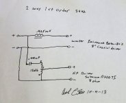
This is OKPerhaps this crude LTSpice model will help you understand the differences between an autoformer and an lpad as far as the resulting voltage transfer function. I'm using a model of a Klipsch T2A autoformer and using it's -3.35db tap.
The middle circuit is a typical Klipsch high pass circuit to the squawker. It's the green plot. It's a little hard to see, but it starts around -44db.
The top circuit is an lpad circuit set to -3.35db. Because the T2A increases the load on the 13uf capacitor (14.6*2.162, or 31.57), I need to use a 28.114uf capacitor in this circuit. It's the top red plot. However, the 21.1mh inductance between tap00 and tap04 is missing. In order to get the same plot (the lower red plot really close to the green plot), I needed to add a 21.1mh inductor across the driver.
The bottom circuit incorporates a swamping resistor. I chose a value that, in parallel with the reflected impedance of the autoformer (31.57 ohms), brings the load on C3 back to 14.6 ohms. Notice the blue plot, as it now appears as if a parallel 44.8mh inductor is across the driver. 44.8mh is the inductance between Tap00 and Tap05.
Mike
View attachment 1139858View attachment 1139859
BUT try to put as the load more complex speaker spice model. Because that is the complex RLC condensed circuit. NOT only passive resistace like 4ohms or 8ohms...
Because of the more accurate graph AND phase...
+
with every inductive att. have to place bypass R of 47-120ohms in parallel with input (maximum) tap - GND.
Try to simulate W/WO.
And measure after that to confirm. I did, and more dramatic diff are in real world. As with SPL and phase as the sound outcome.
it did not worry PWK in the days of what are now called his "Heritage" line of 3-ways speakers who shared the same autoformer and choke throughout Heresy to Klipschorn. For those who like to play with boutique capacitors where there's serious attenuation, there can be some money saved (vs a larger cap) as the capacitor value will be smaller. Bob Crites (RIP) IIRC used about 0.5uF highpass to the Klipsch style autoformer for a Selenium D220. A swamping resistor could be employed, necessitating a larger cap.
Some test leads and RTA would sort things out about as fast or faster than mucking with an adjustable L-pad and fixed resistors.
Resistive pads should perform better. PWK thought the rise in Z in the midrange such as one would see with a Heresy may have reduced distortion. (probably a Crown - Klipscheads would know)
Attachments
Last edited:
yes it is extremely obvious to a trained eye, especially in conjunction with the picture having as reference the white lighter! To the point now! If you are prepared to use big cores you can use the “E” part of a simple EI type trafo, I do not think you really need an extremely nice and expensive core to built a tapped inductor of mHy value. without the ”I” part it gets even better because it is a lot harder for the inductor to saturate.You probably refer to 25Hy it was my typo mistake, It should be 25mHy. But that is so obvious? Especially with the picture of used wire?.. 🙁
I corrected the post units 1-2 posts after i dint saw it because it was not recently...yes it is extremely obvious to a trained eye
.
You can use just EI laminations BUT the inductance will be much much insuficiant. Target is about 25-35mH and low Rdc
With just E cores You have to increase the core Area in cm2. As the consequence increases the length of 1 winding, maybe even 2X
that lead to double increased Rdc.
.
You dont need to tighten the laminations. Put them just like to fit in tha core wthout force, by hand. That will increase inductance.
.
Because of the absence of DC pre-magnetisaton, only AC signal are running in the L-att, there are no that DC component for magnetization,
Eventually You can calculate Voltage for max. Driver power. AND with that voltage calculate max. induction, You can use 1[T] or 0.707[T].
From that You will have a max and optimum nuber of turns for total L.
Next step is to calculate -db taps against the number of turns...