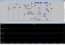
(below 1 ) is my best attempt at a "blameless line stage".
By "blameless" I mean ... these specs don't matter -
.5ppm and -210db psrr !!! (below 2/3).
The Jung super reg was a "beatch" , it oscillated on some op-amp
models and not on others ... as it was originally published.
So , I treated it as a feedback amp , broke the loop - and optimized
it for phase margin and bandwidth. In doing so , I had to compromise
between performance and stability (like in my amps). 😉
My Jung did not have the LF PSRR of the original , but had superior HF
performance ..... added a CRC instead of that LM317.
In the end , I have the Jungs performance , add my line stage for
that -210db pssr ... plus ,ANY IC will work ! (in either PS or amp).
"Roll yer' chips in my designs !! 😀
Edit - this is for analog ... for digital , a mosfet reg. is the way (noise performance).
OS
Is the Jung regulator ready for PC board or is it still going to get some more refinement? Should R6 be a trim pot?
Is the Jung regulator ready for PC board or is it still going to get some more refinement? Should R6 be a trim pot?
Yes , here is the "tidy" positive version (below/ R7 = 10-20V).
I just tried just about every LT op-amp in this circuit. All are stable and
between -115db and -125db PSRR.
As I said before ,
- LM317 = -72
-7812 = -52
- a Discrete LTP error amp with reference @ -65db.
This is such an easy circuit , you should build it and scope it. Give it
a 15R load (1A) .... that is it's limit. ( 2 picovolt load change !! )
I'll make the inverse negative version next.
Both the reg's and the two buffer
amps should be anally laid out on one board.
Just two of these PS's could also supply any other analog requirements.
PS - Q2 needs a BIG heatsink for 1A. (or chassis mounting).
What I did was trade off 20db in performance for stability/simplicity.
The original did >-140db !
You are a morning person , jeff ?? 😛
OS
Attachments
I usually start my day around 4:30 or 5. Not a morning person, insomniac.Yes , here is the "tidy" positive version (below/ R7 = 10-20V).
I just tried just about every LT op-amp in this circuit. All are stable and
between -115db and -125db PSRR.
As I said before ,
- LM317 = -72
-7812 = -52
- a Discrete LTP error amp with reference @ -65db.
This is such an easy circuit , you should build it and scope it. Give it
a 15R load (1A) .... that is it's limit. ( 2 picovolt load change !! )
I'll make the inverse negative version next.
Both the reg's and the two buffer
amps should be anally laid out on one board.
Just two of these PS's could also supply any other analog requirements.
PS - Q2 needs a BIG heatsink for 1A. (or chassis mounting).
What I did was trade off 20db in performance for stability/simplicity.
The original did >-140db !
You are a morning person , jeff ?? 😛
OS
You want the buffer on the same board with transformer externally mounted elsewhere or should the whole supply be separated from the buffer? Is it better to bring unfiltered AC through the preamp chassis and risk emitting noise or bring filtered DC through the chassis and risk picking up noise?
I usually start my day around 4:30 or 5. Not a morning person, insomniac.
You want the buffer on the same board with transformer externally mounted elsewhere or should the whole supply be separated from the buffer? Is it better to bring unfiltered AC through the preamp chassis and risk emitting noise or bring filtered DC through the chassis and risk picking up noise?
RF filter at AC input , trafo either separated by distance or shielded.
The reg's actually should go right close to the buffers. On Jung's design,
R6 ( rail sense/ feedback) could attach right at the load (the buffer outputs).
This way, even the inductance's of the traces would be encompassed
by the error amp's feedback loop.
Grounding should be full star style for the whole combined PS/Buffer PCB.
With the 1A available from each PS unit , a euro-terminal could be used
to derive the +/- 15V for further regulation by 3 terminal devices.
Combined , the stereo buffers would only use 250ma , leaving >1/2A
for any other linear needs - like the DAC output op-amps.
The digital supply should be a truly separate deal (trafo , rectifier , MOSFET
shunt regs.).
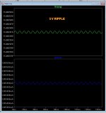
PS - you could wrap this PS with the AC cord , and it would reject it all !!
Edit - Below - with 5 volt ripple .... still 2 picovolt !
OS
Attachments
Last edited:
What do you think of rectifying the ac at the transformer and placing the first filter caps of the CRC filter there. Star quad shielded cable from there to the buffer/regulator board?
What do you think of rectifying the ac at the transformer and placing the first filter caps of the CRC filter there. Star quad shielded cable from there to the buffer/regulator board?
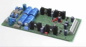
That would require an extra board ? Trafo/bridge/both big caps-R1....
Then just a local 10uF at the super -regulator.
I did sim with a rather high serial resistance , the regulator did not care.
(below) .... most of the Jungs out in the wild have the unregulated
onboard , the better ones with a separate trafo. Some chinese or diy
ones integrate the trafo on-board. Yuk !
OS
Attachments
The rectifier board would be small enough that it would be $13/dozen.That would require an extra board ? Trafo/bridge/both big caps-R1....
Then just a local 10uF at the super -regulator.
I did sim with a rather high serial resistance , the regulator did not care.
(below) .... most of the Jungs out in the wild have the unregulated
onboard , the better ones with a separate trafo. Some chinese or diy
ones integrate the trafo on-board. Yuk !
OS
I like thos little pc mount toroidals. Nice and compact package without a lot of extra wire.
Last edited:
why no over current protection? pri/sec fuses only?
you have that crc, use the r to sense and shutdown the supply. i will give you my sim to look at.
input emi filter?
picking the correct pass bjt type issue = try a mosfet 🙂
did you even try/look at the mosfet?
try
Schurter dc21 AC Power Entry Modules | Mouser
ac remote control? is there going to be a mcu in pitchfork?
you have that crc, use the r to sense and shutdown the supply. i will give you my sim to look at.
input emi filter?
picking the correct pass bjt type issue = try a mosfet 🙂
did you even try/look at the mosfet?
good idea, how about adding the ac input, filter & switch tooI like those little pc mount toroidals. Nice and compact package without a lot of extra wire.
try
Schurter dc21 AC Power Entry Modules | Mouser
ac remote control? is there going to be a mcu in pitchfork?
Attachments
Mine's getting a modefied version of the amp control board and will also be telling the amp to turn on.
why no over current protection? pri/sec fuses only?
you have that crc, use the r to sense and shutdown the supply. i will give you my sim to look at.
input emi filter?
picking the correct pass bjt type issue = try a mosfet 🙂
did you even try/look at the mosfet?
good idea, how about adding the ac input, filter & switch too
try
Schurter dc21 AC Power Entry Modules | Mouser
ac remote control? is there going to be a mcu in pitchfork?
At 1.1A you drop to 13V . 1.25A - 4V. At this point the reference loses
sufficient voltage and the whole regulator collapses to a safe >2.5V level.
A dead short will output < mv.
Regulator is self limiting by design. 🙂
Jeff's protection board , in a simple form (tiny relays for soft start/on)
would be good. Just using the delay for the output buffers would be nice.
The buffers (either mine or the IC one) , also are current limited at @200ma.
OS
This linestage is awful close to Dadod's MK2 preamp.
Is the LT1028 the preferred op amp of would one of the BB OPAs be a better choice?
Is the LT1028 the preferred op amp of would one of the BB OPAs be a better choice?
I know that OS says any opamp will work with this design but wouldn't using the lowest noise opamp be appropriate here? Something like the opa604 from TI, formerly a B-B part.
some say that LME49710 would work good with the LME49600 as is suggested also on the spec sheet.
I did that one , I even made a full discrete error amp with a series current
source and the shunt controlled by the differential.
NOT EVEN CLOSE to the IC error amp Jung. (-60db vs -120+db).
The Jung can also be ported to control a shunt with the lowly
317 as the current source , as well.
Just simulated , evaluated , and modified 50 "super regs" ...
the Jung wins - hands down.
PS - yours will work ... but only do -50- -60db.
edit - did the salas , better noise ... but not PSRR.
OS
OS
Thanks for your comment; it seems then that this shunt circuit appears to be worse than the 317/337 which can go all the way to -80dB when correctly implemented?
Should we do separate regulators for each linestage monoblock style or share it for both channels?
some say that LME49710 would work good with the LME49600 as is suggested also on the spec sheet.
I can't for the life of me understand why so many people are impressed with the sound of the LME49600, or even the LME49710 as far as that goes. I've tried the 49600 with several op-amps(National, Burr Brown, LT, etc..) in front of it and wasn't impressed with the sound quality at all.
The sound quality's not even in the same league as the TPA6120.
If I were building a "high performance" preamplifier, I would look elsewhere for a better buffer for it than the 49600.
Even Calvin's little discrete buffer blows away the 49600 when it comes to sound quality.
Last edited:
Sorry for the confusion, I wasn’t implying to use the 49600, OS at one point was looking for the best opamp to go with his discrete line amp which he said was similar to the 49600 block schematic and I was pointing to the LME49710 for the reason explained.
BTW, I have no experiance with the 49600 so can't comment on that.
Good input Ammel.
BTW, I have no experiance with the 49600 so can't comment on that.
Good input Ammel.
Last edited:
At what frequency you guys refer to theoretical PSRR? 1-2MHZ? My simulation for non cascoded IRF9610 LED biased CCS (with single JFET CCS for the LEDS) gives -60dB @ 2MHZ for instance and -126dB in the audio band.
P.S. Here are the real measured PSRR figures for several ones as done by Jack Walton for Linear Audio Magazine (LM317 included) http://linearaudionet.solide-ict.nl/sites/linearaudio.net/files/V4 JW F5.pdf
I foud this:
http://www.designers-guide.org/design/bypassing.pdf
It is a very intresting text about capacitors use .. bypass .. decoupling .. and so on ....
If the project use ultra low noise power supply .. the layout will also be critical to get the best from these power supply.
http://www.designers-guide.org/design/bypassing.pdf
It is a very intresting text about capacitors use .. bypass .. decoupling .. and so on ....
If the project use ultra low noise power supply .. the layout will also be critical to get the best from these power supply.
- Home
- Source & Line
- Analog Line Level
- Pitchfork pre-amplifier