Not quite like you Rsavas !
I had no problem reverse engineering my 1k arduino code.
Arduino is for dummies , everything in the environment is setup for
their dev boards.
Way bigger learning curve with the AVR (by raw , I meant basic like)
well i can say once you get your feet wet with bascom-avr, you will think differently. i looked at both of them in the beginning and chose what would be the shortest path to success and bascom-avr was it by a long shot. you have to factor in support, ease of use, code reuse,libraries etc. at the end of the day it comes down to bit bashing of registers, does not matter if it is done in c, basic, asm, all do the same thing
Last edited:
If you hire someone to open and close the switch you probably don't need the neck strap.
If this turns out as well as your other endeavours we will all benefit.
Thanks again and again..............
If this turns out as well as your other endeavours we will all benefit.
Thanks again and again..............
Arduino is a wrapper around (gcc) to add an extra level of abstraction to make it a bit easier to start with. it gets you going but does shelter you from the understanding of the mcu architecture and register access = no free lunch
Bascom-avr
Code:
// Assign names to the pins
const int PowerLED = 4;    // LED Bright LOW
const int Inrush = 5;      // InRush HIGH
const int PowerOn = 6;     // Power On HIGH
const int SpeakersOn = 7;  // Speakers On HIGH
const int HeatingOn = 11;  // Heating On HIGH
const int PowerSwitch = 8;    // Power Switch LOW Input
const int DCoffsetAlarm = 0;  // DC Offset Alarm LOW Input Interrupt0
const int OverloadAlarm = 1;  // Overload Alarm LOW Input Interrupt1
const int ACFailureAlarm = 9; // AC Failure Alarm LOW Input
const int OverheatAlarm = 10; // Overheat Alarm LOW Input
const int Bad = 0;
const int Good = 1;
// Setup routine runs once at protection board power-on
void setup() {
  //Init the pins
  pinMode(PowerLED, OUTPUT);
  digitalWrite(PowerLED, HIGH);

  pinMode(HeatingOn, OUTPUT);
  digitalWrite(HeatingOn, LOW);

  pinMode(Inrush, OUTPUT);
  digitalWrite(Inrush, LOW);

  pinMode(PowerOn, OUTPUT);
  digitalWrite(PowerOn, LOW);

  pinMode(SpeakersOn, OUTPUT);
  digitalWrite(SpeakersOn, LOW);

  pinMode(PowerSwitch, INPUT);
  pinMode(ACFailureAlarm, INPUT);
  pinMode(OverheatAlarm, INPUT);
}
Bascom-avr
// Assign names to the pins
const PowerLED = 0 ' LED Bright LOW
const Inrush = 1 ' InRush HIGH
const PowerOn = 2 ' Power On HIGH
const SpeakersOn = 3 ' Speakers On HIGH
const HeatingOn = 4 ' Heating On HIGH
const PowerSwitch = 5 ' Power Switch LOW Input
const DCoffsetAlarm = 6 ' DC Offset Alarm LOW Input Interrupt0
const OverloadAlarm = 7 ' Overload Alarm LOW Input Interrupt1
const ACFailureAlarm = 0 ' AC Failure Alarm LOW Input
const OverheatAlarm = 1 ' Overheat Alarm LOW Input
const Bad = 0
const Good = 1
sub setup() 'void setup() {
' // Setup routine runs once at protection board power-on
'//Init the pins
config portd.PowerLED = output 'pinMode(PowerLED, OUTPUT);
set portd.PowerLED 'digitalWrite(PowerLED, HIGH);
config portd.HeatingOn = output 'pinMode(HeatingOn, OUTPUT);
reset portd.HeatingOn 'digitalWrite(HeatingOn, LOW);
config portd.Inrush = output 'pinMode(Inrush, OUTPUT);
reset portd.Inrush 'digitalWrite(Inrush, LOW);
config portd.PowerOn = output 'pinMode(PowerOn, OUTPUT);
reset portd.PowerOn 'digitalWrite(PowerOn, LOW);
config portd.SpeakersOn = output 'pinMode(SpeakersOn, OUTPUT);
reset portd.SpeakersOn 'digitalWrite(SpeakersOn, LOW);
config portd.PowerSwitch = input 'pinMode(PowerSwitch, INPUT);
config portc.ACFailureAlarm= input 'pinMode(ACFailureAlarm, INPUT);
config portc.OverheatAlarm = input 'pinMode(OverheatAlarm, INPUT);
end sub '}
Last edited:
being used by so many (arduino), there are some clever ways around it (the slowness of the digital I/O functions) ... Fast digital I/O for Arduino - CodeProject
wow "4 microseconds" for simple port bit set/reset op, a two line asm instruction, what a lot of baggage, worse than i even imaginedIt is rather well known that the functions for digital I/O in Arduino are quite slow. It takes about 4 microseconds to change the logical level of an output pin (for example, to turn on an LED) using the Arduino digitalWrite function, while it takes less than 0.1 microsecond if you write the code 'natively', using the I/O registers of the Atmel AVR microcontroller (which is the brain of the Arduino board). Sure, for most users it does not matter whether it takes 0.1 or 4 microseconds, it is still fast enough, but there are situations where the speed or power consumption are critical.
SBR r23,128 ; set bit 7 in reg r23
STS PORTG, R23 ; move reg r23 into port g output reg
bascom
set PORTG.7
Last edited:
Next step - PS /buffer / jung super regulators.
Why not go all out on the output and PS ?
I considered the LME49600 smd . it's nice ... but what if they just want
a headphone amp/line stage ? ....
Or , for some fear of SMD ... choose to do "blasphemy" and mate with a
chinese ebay kit ? 🙁
All discrete , the 317's , the jung regulator op-amps , the buffer op-amps.
Here in the forum ... they love to "roll op-amps" (socketed dip replacement).
For the analog , why not allow for this "fetish" ? Can't do that with SO n /tr packages.
Most of the analog will have to be through hole by design.
PS - tap those Jung's for any analog requirements on the digital boards,
the buffer's won't make a bit of ripple with that level of regulation.
OS
Question and maybe some of you already know, I don't.
If something already exists...and is already compiled and working...
...don't they make (for lack of a proper term) de-compile code writers?
That is, something that looks at the compiled code, then writes generic
code, that we/you can then use to write, then compile new code which
doesn't infringe on intellectual property?
Or
Even though I detest it, why not have a country that doesn't
share our intellectual property rights just make us some of
what ever it is we need?
Here is the difficult part, if it not sold and there are no
profits and it's for educational purposes or for learning...
...imagine if the code worked even though it was
making a mokery of the real thing...(term for this under fair use but
I'm having a senior moment)
someone just might pull it off and we could all get
the chips before everyone got enough for everyone else.
It's how Sesame Street used La Bamba, with out having
to pay royalties, on it's learning DVDs. I bought one for
my little kid and couldn't believe they got away with it.
They have the guitar player singing to little sheep,
Baaa, Baaa, Bumba....etc. I could almost imagine
the parody in the comment section of the code...
I feel shamed for having to write that...but worse things
have been done.
We might as well get something that will benefit
all us DIYers here...legally.
Always worry about lawyers when they start talking ethics
and morals. Don't ask me how I know.
Yes of course i can,i had make this with original hex.
I had used a pic18 development board and the MPLAB.
Thanks for your interesting ,i will open a new thread for this.
I had used a pic18 development board and the MPLAB.
Thanks for your interesting ,i will open a new thread for this.
Please keep this in mind
Gents,
Please keep Speed of button pushing in mind.
I've got Uverse and hate it with a passion.
Worst of all are when you push the buttons they
are programmed for some slow speed!
If you push 1013 quickly....ATT UVerse receiver reads 10 or 03.
If you want to do another function...Like set a favorite channel
and you do it too quickly on the buttons....the receiver misses
half of it. Or maybe it is the transmitter can't process the human
pressing the buttons too quickly.
Same as any of us with the digital clock. We cannot keep pressing the buttons
to speed up changing the time. We have to Press and agonizingly hold
the button down for 1/2 a second for it to change the time for one second.
Okay, maybe it is 1/8 of a second for each change. But it sure seems to
take forever.
Please make it fast button pushing recognizing.
"1) start a new thread and we can discuss it there"
Here it is. http://www.diyaudio.com/forums/software-tools/272988-jal-language-help.html#post4292636
Here it is. http://www.diyaudio.com/forums/software-tools/272988-jal-language-help.html#post4292636
hey OS, check out this pre-amp design by Mile "Apex" P30, might be of use to you.Most of the analog will have to be through hole by design.
terry (still4given) has made the two different layouts and is testing them out.
Since it is of such hi performance, i suggest to use a motorized volume pot,
terry drew up the sim and i added some changes in the post here.
http://www.diyaudio.com/forums/solid-state/164093-100w-ultimate-fidelity-amplifier-462.html
post #4612
lets see what you think
hey OS, check out this pre-amp design by Mile "Apex" P30, might be of use to you.
terry (still4given) has made the two different layouts and is testing them out.
Since it is of such hi performance, i suggest to use a motorized volume pot,
terry drew up the sim and i added some changes in the post here.
http://www.diyaudio.com/forums/solid-state/164093-100w-ultimate-fidelity-amplifier-462.html
post #4612
lets see what you think
I'm stuck on regulators now ....
317's = -72db
Some discrete error amp based ones = -90db
The "Jung" = -140db ( but it is on the edge of stability).
I'm trying to "harden" the jung.
Yeah ...the p30 is nice , for "too many" transistors. 🙄
-easily beat by a LME49600 (still might go this route) and a
OPAxxxx.
OS
i know lots of bjt's in ap30.
checkout that low noise regulator using the mosfet, that i have in the digital page of my pre-amp design. it is from a maxim app note, nV's of noise.
checkout that low noise regulator using the mosfet, that i have in the digital page of my pre-amp design. it is from a maxim app note, nV's of noise.
Full deal - any parts (not "picky") !!
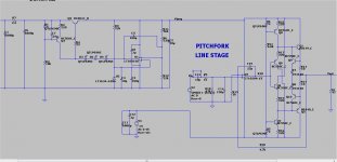
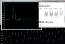
(below 1 ) is my best attempt at a "blameless line stage".
By "blameless" I mean ... these specs don't matter -
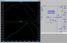
.5ppm and -210db psrr !!! (below 2/3).
The Jung super reg was a "beatch" , it oscillated on some op-amp
models and not on others ... as it was originally published.
So , I treated it as a feedback amp , broke the loop - and optimized
it for phase margin and bandwidth. In doing so , I had to compromise
between performance and stability (like in my amps). 😉
My Jung did not have the LF PSRR of the original , but had superior HF
performance ..... added a CRC instead of that LM317.
In the end , I have the Jungs performance , add my line stage for
that -210db pssr ... plus ,ANY IC will work ! (in either PS or amp).
"Roll yer' chips in my designs !! 😀
Edit - this is for analog ... for digital , a mosfet reg. is the way (noise performance).
OS
(below 1 ) is my best attempt at a "blameless line stage".
By "blameless" I mean ... these specs don't matter -
.5ppm and -210db psrr !!! (below 2/3).
The Jung super reg was a "beatch" , it oscillated on some op-amp
models and not on others ... as it was originally published.
So , I treated it as a feedback amp , broke the loop - and optimized
it for phase margin and bandwidth. In doing so , I had to compromise
between performance and stability (like in my amps). 😉
My Jung did not have the LF PSRR of the original , but had superior HF
performance ..... added a CRC instead of that LM317.
In the end , I have the Jungs performance , add my line stage for
that -210db pssr ... plus ,ANY IC will work ! (in either PS or amp).
"Roll yer' chips in my designs !! 😀
Edit - this is for analog ... for digital , a mosfet reg. is the way (noise performance).
OS
Attachments
Last edited:
OS
This could be another option. Nothing fancy as Salas regs but this is a simple shuntreg, with the aid of LM431, that could be use on some circuits of the preamp/headphone amp. Add a couple of film caps to stabilize the Ref voltage on de 431.
Have not tested it yet, hope is a working one.
This could be another option. Nothing fancy as Salas regs but this is a simple shuntreg, with the aid of LM431, that could be use on some circuits of the preamp/headphone amp. Add a couple of film caps to stabilize the Ref voltage on de 431.
Have not tested it yet, hope is a working one.
Attachments
OS
This could be another option. Nothing fancy as Salas regs but this is a simple shuntreg, with the aid of LM431, that could be use on some circuits of the preamp/headphone amp. Add a couple of film caps to stabilize the Ref voltage on de 431.
Have not tested it yet, hope is a working one.
I did that one , I even made a full discrete error amp with a series current
source and the shunt controlled by the differential.
NOT EVEN CLOSE to the IC error amp Jung. (-60db vs -120+db).
The Jung can also be ported to control a shunt with the lowly
317 as the current source , as well.
Just simulated , evaluated , and modified 50 "super regs" ...
the Jung wins - hands down.
PS - yours will work ... but only do -50- -60db.
edit - did the salas , better noise ... but not PSRR.
OS
Not too well , not enough current gain @ 750ma load. It might work with a smaller base stopper and lower current on the CCS. (and less load).
The MJE just requires too much base current with any load (just simulated
it).
Low Vceo devices rule for the Jung regulator.
OS
The MJE just requires too much base current with any load (just simulated
it).
Low Vceo devices rule for the Jung regulator.
OS
So it need low Vceo and high current gain. What other BJT i can use ?
Tip 42 might do it.
The D44 , if you look at the Hfe curve <2A , rises to @ 200Hfe.
The Tip's are 100 at any Ic.
Don't look at the printed rating (min/max) , look at the Hfe/Ic graph
in the <1A "zone".
OS
- Home
- Source & Line
- Analog Line Level
- Pitchfork pre-amplifier