P.S. Here are the real measured PSRR figures for several ones as done by Jack Walton for Linear Audio Magazine (LM317 included) http://linearaudionet.solide-ict.nl/sites/linearaudio.net/files/V4 JW F5.pdf
I tried yours , Salas ... It was almost even with my Jung.
I chose the Jung for the efficiency.
My results were VERY similar , but some better at >1mhz.
(tried em' all) ...
I also simulated one diamond line stage with the Jung , even with that active
>200ma class A load , another channel would (not be affected).
4 jung's for the stereo line stages would still be cheap (and cool).
I was just thinking of streamlining both line stages and both DAC
analog power requirements to a set of (+/-) Jung's.
OS
I suppose dual mono would not be any more difficult - but would we
hear it at over - 150db+ ( any op-amp hook ed to the Jung) ??
OS
I've got a stereo linestage almost ready for testing.
A combination of op-amps and discrete devices?
I've got a stereo linestage almost ready for testing.
That looks like a lot of loop area between the linestages and power supplies.
There is no way to make it symmetric ?
What I mean is the positive regulator close to the two positive class A
output devices - same rail.
Think of an output stage on a big amp with two pairs - each pair driven
by it's own individual set of diamond buffers and running off the same
common V+ and V- bus.
Grounds could return to the middle symmetrically.
The Jung's give us the option of a slightly unsymmetrical rail layout , as the
error amp feedback can compensate by it's takeoff point.
Ground layout should still approach symmetry (for cancellation).
Show the major tracks , like I do on a new IPS.😀
OS
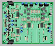
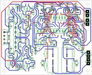
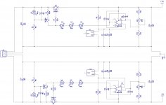
This software is pretty hard to show a board. I've removed the ground plane to show traces. I think I should be sensing the supply right at C15 and C16. It's pretty tough to feed both channels symmetrically from one supply so I moved the output caps from the supply right to the output stage. That leaves a long loop in the negative rail output. There's going to be a long loop somewhere no matter what. Is that better to be in the raw DC input or in the output of the supply?
Attachments
This software is pretty hard to show a board. I've removed the ground plane to show traces. I think I should be sensing the supply right at C15 and C16. It's pretty tough to feed both channels symmetrically from one supply so I moved the output caps from the supply right to the output stage. That leaves a long loop in the negative rail output. There's going to be a long loop somewhere no matter what. Is that better to be in the raw DC input or in the output of the supply?
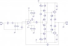
You want the shortest path possible between Q9/10 /18/17 and the regulator
pass transistors. The regulator error sense inputs - R11/14 , should connect
midway between (or on a thicker common bus) going to those line stage
outputs.
Pass transistors/line stage outputs - where any real current will be flowing.
The ground returns of these "players" should also be short,sweet, and symmetrical.
Why not have a set of euro terms with the jung regulated outputs. The load
on the regulators is almost resistive and the regulators will have
a full .5 -.75A "left over" ????
PS - you realize this could also be a very nice headphone amp with the
addition of a input volume pot ?? (external . of course 😀 ).
Edit - all grounds through the plane ??? Nah , digital maybe - this is analog
(anal analog).
ground returns on the ips's , slewmaster ops decoupling are how you get
"nasty" currents to behave.
OS
OS
Last edited:
You want the shortest path possible between Q9/10 /18/17 and the regulator
pass transistors. The regulator error sense inputs - R11/14 , should connect
midway between (or on a thicker common bus) going to those line stage
outputs.
Pass transistors/line stage outputs - where any real current will be flowing.
The ground returns of these "players" should also be short,sweet, and symmetrical.
Why not have a set of euro terms with the jung regulated outputs. The load
on the regulators is almost resistive and the regulators will have
a full .5 -.75A "left over" ????
PS - you realize this could also be a very nice headphone amp with the
addition of a input volume pot ?? (external . of course 😀 ).
Edit - all grounds through the plane ??? Nah , digital maybe - this is analog
(anal analog).
ground returns on the ips's , slewmaster ops decoupling are how you get
"nasty" currents to behave.
OS
OS
Should the regulator grounds be on their own star? I'll play with this some more when things slow down a bit. I'm going strong on the I/O control design right now.
Did you ever narrow down your choices on a DA converter?
Should the regulator grounds be on their own star? I'll play with this some more when things slow down a bit. I'm going strong on the I/O control design right now.
Did you ever narrow down your choices on a DA converter?
The regulator grounds to a perfect star , the ground plane will act as a faraday shield/cage if connected to the center of the PS star.
But , any component grounded to the plane might also pick up EMF/RFI 🙁.
Also , the reference grounds and the error amp divider on the Jung want to see the same perfect ground (the main PS star). Separate returns for these , too.
Please , output the regulators (euro-terms) 😀 ....
OS
Okay. Can you see any changes happening to the linestage? Should I add any pads for caps anywhere?
Okay. Can you see any changes happening to the linestage? Should I add any pads for caps anywhere?
http://www.ti.com/lit/ds/symlink/lme49600.pdf
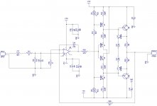
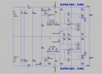
See the 10uf's at the 49600 ? Those are the ones at the output of the Jung.
These should be at the linestage output collectors instead.
These were included in the PS schema to test for stability.
Just consider the discrete linestage like a big 49600.
OS
http://www.ti.com/lit/ds/symlink/lme49600.pdf
See the 10uf's at the 49600 ? Those are the ones at the output of the Jung.
These should be at the linestage output collectors instead.
These were included in the PS schema to test for stability.
Just consider the discrete linestage like a big 49600.
OS
I added some right at the outputs (C31-34) to decouple them from the other channel. I left the regulator output caps (C15 & 16) as well. I also added electros and ceramics on the op amps on the inputs. I'm just wondering if there will be any compensation caps on the outputs or predrivers.
I fed the input sections from the output collectors. Should they be fed from there or from the caps on the Jung outputs?
Last edited:
I added some right at the outputs (C31-34) to decouple them from the other channel. I left the regulator output caps (C15 & 16) as well. I'm just wondering if there will be any compensation caps on the outputs or predrivers.
I fed the input sections from the output collectors. Should they be fed from there or from the caps on the Jung outputs?
What I meant , was that you don't need them at the Jung's output. I put them
in the schema for a stand alone regulator. Hooked to the linestage , the 10uf's
go to the linestages outputs (where they count).
If the PS was stand alone , an "unknown" dynamic load might require that
decoupling.
Edit- you might want to add one optional SM cap placement from (-) to (out) for the linestage IC.
OS
Last edited:
I'll have to ask Jeff that tomorrow ...
I could build /simulate quickly in the morning ...
How did he convert the negative? ... and is it simulated ?
OS
I could build /simulate quickly in the morning ...
How did he convert the negative? ... and is it simulated ?
OS
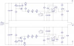
Did it - perfect !
Check it to yours , Jeff. (below)
Edit , non-inverting IC inputs have to be hooked to the reference on both !
Inverting to the FB loop (sense).
OS
Check it to yours , Jeff. (below)
Edit , non-inverting IC inputs have to be hooked to the reference on both !
Inverting to the FB loop (sense).
OS
Attachments
Last edited:
I'm missing the diodes on the op amp inputs in my schematic. Is your negative rail op amp inputs connected properly? I've been messing with op amps for years but still get the inputs backwards half the time.
- Home
- Source & Line
- Analog Line Level
- Pitchfork pre-amplifier