J1 can/will be used for local +/- 5v (further regulation) at a DAC or attenuation
PCB. So , longer traces will be no issue with local decoupling in that case -
it will feed wires !
That layout looks real good , similar to the better PCB kits I've seen.
OS
I think the PGA2310 needs +-15VDC so it would be good there. When you say DAC, do you mean for analog out or for digital too?
I'm the same. Big flashy screens and blinking LEDs are too much of a distraction. It's nice not having to get up to adjust the volume though.
Remote input selection and volume would be all I need.
A front panel "over-ride" , in case you lost your remote.
All my "flashy" stuff is right on my PC/HDTV , I can view FFT's and
oscilloscopes of my audio in 1080P ! 😛
OS
hey man i am chilled because I am buzzed, just offering info/ideas to make life easy for you guys, since i and many others have done it already.
I was wrong, bryan/amb have released their code and i am going through it now, while watching hockey with Mom.
He scores, Mom ah ****!!
i can say danzup code is 99% simpler, to me at least, to do the same thing essentially.
good luck with your project.
I was wrong, bryan/amb have released their code and i am going through it now, while watching hockey with Mom.
He scores, Mom ah ****!!
i can say danzup code is 99% simpler, to me at least, to do the same thing essentially.
That's cool, you can lug your PC/big screen TV along with your tunes 🙂All my "flashy" stuff is right on my PC/HDTV , I can view FFT's and oscilloscopes of my audio in 1080P !
good luck with your project.
Last edited:
I think the PGA2310 needs +-15VDC so it would be good there. When you say DAC, do you mean for analog out or for digital too?
PCM1794-8 needs +/-15V for the DAC diff. /summing-filter op-amps. TI
actually recommends NE5534 as the op-amp !! 😱
But they say -123db noise and 5ppm THD is achieved.
The whole PCM17xx line then just needs a low noise 5V and 3.3V digital
Supply.
The +/- 5V supplies would be for the attenuation (PGAxxxx).
The PGA also needs a clean 5V digital supply.
So , all the analog from the Jung's and a separate digital supply for the 3.3/
5V.
You notice no response to my explanation of my "blasphemy" to the Jung
regulator 😀 .
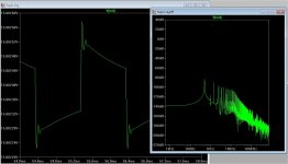
But it's true (below) ... the original would "croak" on the 6V squarewave
shown. That's all the ringing I could get out of it (without a CRC , even).
You can use a TIP142/147 as series device for a nice -125db PSRR (1.5A out).
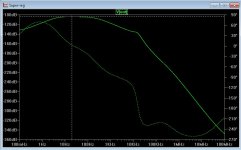
The whole range was -115db to -127db , with any op-amp or BJT -
NO oscillations ... at all.
PS - I'm not sure the regulators designers put the circuit though the
"hell" I did. It is just a simple neg. feedback circuit , with the reference as the
"pesky" positive component. After identifying this , I treated it as such.
Edit - we use this instead of a LM317 ... why ?? (below 2) , it even makes a ZENER
reference look good at -102db ! Truly "pitchfork" ... junk drawer bliss !
OS
Attachments
Last edited:
I've been waiting to see if anyone responded to your design. What voltage do we need to feed the regulator? Will it run on 24-0-24VAC?
hey man i am chilled because I am buzzed, just offering info/ideas to make life easy for you guys, since i and many others have done it already.
I was wrong, bryan/amb have released their code and i am going through it now, while watching hockey with Mom.
He scores, Mom ah ****!!
i can say danzup code is 99% simpler, to me at least, to do the same thing essentially.
That's cool, you can lug your PC/big screen TV along with your tunes 🙂
good luck with your project.
I don't usually go mobile with music , driving/walking is best done in
silent perfection .... no distractions -accidents !
"Headphone Zombies" are such easy targets (and hazards , as well).
I watched one get eaten by a bear.
OS
I've been waiting to see if anyone responded to your design. What voltage do we need to feed the regulator? Will it run on 24-0-24VAC?
Another plus , you could run these off the Slewmaster supplies. 😱
The led current source and series BJT are the only things that see the
unregulated input.
Another point of this regulator is startup. The original zener assured that
a "railed" op-amp output would not be needed to set the series transistor
bias - hence , "this is absolutely essential" comment. My 3 leds are close
, 3 greens would almost copy the original 6.7V zener ,but reds are quieter.😀
I have a nice 18-0-18vac 200VA if this works out. 🙂
OS
Cool. I saw you were simulating with 25VAC and got worried we wouldn't be able to find a transformer.😀
I did not mean walkman zombie.
we used to drive our stereo to parties as kids because we had the best one, of the group, at that time. it fit perfectly in the back seat of dad's '70 chevelle malibu. turntable on the front passengers lap, records in the trunk, away we go, to the next party.
Since knowone else cares to comment i will.
1) I know you like your LEDs, but do you not think a tl431 or equiv, would make a better reference, than a LED, in your current source driven off an unreg supply?
2) No tracking of supplies? only would need one pot if you even need that.
3) do you actually trust a opamp sim model? and that in the real world your ckt will behave the same.
4) can not wait to hear about your comparison of a ne5534a as an DAC I/V compared to whatever else you come up with.
5) you have evaluated and you can do better than TI TPS7A33? Imagine that you can make a better lin reg than TI can 🙂
I sim'd up Apex SB3.1, I will post the sim using it. just for the fun of it.
Attachments
Last edited:
Cool. I saw you were simulating with 25VAC and got worried we wouldn't be able to find a transformer.😀
Yes , it's a small logitec sub trafo - have 2 of them. They both have
18-0-18 to 21.5-0-21.5Vac ( 25-30Vdc unregulated) ....
with handy additional 14V secondaries.
How neat is that ! For the digital ! 🙂
OS
I did not mean walkman zombie.
we used to drive our stereo to parties as kids because we had the best one, of the group, at that time. it fit perfectly in the back seat of dad's '70 chevelle malibu. turntable on the front passengers lap, away we go, to the next party.
I know you like your LEDs, but do you not think a tl431 or equiv, would make a better reference, than a LED, in your current source driven off an unreg supply?
The LED CCS is a start-up facility for the regulator. You want it to be "fast and
dirty".That is also why it's hooked to the unregulated side.
The error amps feedback would even mostly cancel out just a pure resistive
source instead of the led CCS.
PS - Q1 is not the reference , the real reference is hooked to the op-amp (+).
The op-amp (error amp) will also correct thermally for Q1/2 and the led's.
(checked this , too).
PS - stereo to parties 😱 I can now give the party a real show !
HD audio + the video ( pink floyd -pulse , 3 rush live concerts , the wall HD,
100's others) 😎 .
OS
I did not mean walkman zombie.
we used to drive our stereo to parties as kids because we had the best one, of the group, at that time. it fit perfectly in the back seat of dad's '70 chevelle malibu. turntable on the front passengers lap, away we go, to the next party.
I know you like your LEDs, but do you not think a tl431 or equiv, would make a better reference, than a LED, in your current source driven off an unreg supply?
I used to drive my stereos to partys when I was a kid too. My car audio systems used to be worth 10 times as much as the junk I installed it in. I miss driving winter beaters now though. 😀
Little hi for +5V unless you are going to use 12V relays.with handy additional 14V secondaries.
I'd like to review your power control system, what controls what?
All my vehicles are winter beaters, for it does not take them long to become beaters thanks to that GM strong steel and our Windsor salt 🙂
okay i get it now, CC/led is only for start up, opamp takes over in the control loop, swamps out CC. yes I know which one is your v ref 🙂 thx
I guess we need a panel van(shaggin wagon) for your setup 🙂PS - stereo to parties I can now give the party a real show !
HD audio + the video ( pink floyd -pulse , 3 rush live concerts , the wall HD,
100's others)
Last edited:
Tried compiling bryan's code = road block, something to figure out.
So where is
#include "WConstants.h" // all things wiring / arduino
#include <Wire.h>
OS too bad we live so far apart, I'd love to watch some of those videos with you.
So where is
#include "WConstants.h" // all things wiring / arduino
#include <Wire.h>
OS too bad we live so far apart, I'd love to watch some of those videos with you.
The other power supplies ....
Now we need a nice quiet 5V and 3.3V for the digital.
I looked around , (link) - Finesse Voltage Regulator Noise! |
It seems the combo series/shunt (317 / simple shunt). Just sinking the resistor noise current through a BJT , easy !
The 3rd example is said to be able to reduce a 317's noise to 20uV.
So , I looked at what is available from TI. Hmmm ,
- 3.3V = http://www.ti.com/lit/ds/symlink/lp5907.pdf
And the 5V = Any number of TI LDO regs - like http://www.ti.com/lit/ds/symlink/lm2937.pdf
Performance is not much better than a 317 here .....
Better ones are costly or are limited in current. It might be best to go
DIY discrete for the 5V supply.
Any relays can be run from a simple 7812 fixed regulator - no real "audiophile"
factor to worry about.
OS
The relays I'd like to use are 5VDC latching so the current draw from them would be only when changing an input or output selection when everything is muted. 12V would be an option too.
The fun of all the design choices available and the ones that designers make. Nothing like being unique and one of a kind 🙂
In mixed signal design, it is usually the noise generated by the load (digital/switching transients) you are more concerned about getting into the analog system than noise from the PS alone.
The concept of point of load regulation is used in many mixed signal designs to isolate digital noise. Like having a 5V bus and regulate it down to 3.3V in strategic places. I have seen many prefer AMS parts.
Latching relays, you pay a premium on. is it worth it? most would say depends on how many you use of course, is power a design concern? They do save power for sure, but how many relays do you anticipate being on at once, for a worst case?
I myself would stick with the old standard RY-5 sensitive coil in a common footprint.
Last edited:
The relays I'd like to use are 5VDC latching so the current draw from them would be only when changing an input or output selection when everything is muted. 12V would be an option too.
Even as you would just be "glitching" the 5V supply when you changed input ,
maybe a separate "dirty" 7805 regulated relay supply .... as well as the "anal",
low noise one for the digital ?
(or a 12V one).
Edit - as far as relay load / digital load ... that 2'nd 18V secondary is 2A !
I can't foresee even using 1/4 of that.
OS
Last edited:
In mixed signal design, it is usually the noise generated by the load (digital/switching transients) you are more concerned about getting into the analog system than noise from the PS alone.
Two separate sets of power supplies.
For all to see , I'm checking these two (below) for the 5V "clean".
Lower PSRR won't be a problem for digital ... like it is with analog ?
OS
Attachments
I've seen a few DAC designs that run a 12VDC rail around the board to 3V3 and 5V regulators at each pin requiring power but the datasheet's I've been looking at are recommending a common decoupled supply.
- Home
- Source & Line
- Analog Line Level
- Pitchfork pre-amplifier