yes I noticed it. after successfully start with light bulb it will be fine, but without it maybe next day, next month... it will burned at startup.
also NTC needs time to cooldown to reset it's value, rapid on off will burn IGBT
Without light bulb tester(smps directly connected to main voltage) smps burns instantly!
It is something that i haven't tried.....to short the light bulb without to unplung the main voltage.
I will repeat here that PHONIC selling in the past a repair kit.
The NTC, among with others,was in the kit
Who know if it was the original as in the part list or a different one higher ohm(as your recommented is)?
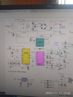
Αll voltages in the secondary were in accordance with the schematic.
+/-54v
+/-35v
+/-15v
+48v
I beleive that there are two posibilities.
1)the IGBT that i used isn't compatible.
2)something was wrong with the delay capacitor(C913=22uf).
In my test circuit smps CAN'T START AGAIN before a delay of about 15''
I had test the repaired smps(with the light bulb connected)and it wasn't any delay time between repeated on-off-on.
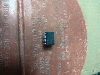
If you will find some free time,please can you compare two IGBT,the on in the part list IRG4PC50W AND the second that i used RGT40TS65D.
also NTC needs time to cooldown to reset it's value, rapid on off will burn IGBT
Without light bulb tester(smps directly connected to main voltage) smps burns instantly!
It is something that i haven't tried.....to short the light bulb without to unplung the main voltage.
I will repeat here that PHONIC selling in the past a repair kit.
The NTC, among with others,was in the kit
Who know if it was the original as in the part list or a different one higher ohm(as your recommented is)?
Αll voltages in the secondary were in accordance with the schematic.
+/-54v
+/-35v
+/-15v
+48v
I beleive that there are two posibilities.
1)the IGBT that i used isn't compatible.
2)something was wrong with the delay capacitor(C913=22uf).
In my test circuit smps CAN'T START AGAIN before a delay of about 15''
I had test the repaired smps(with the light bulb connected)and it wasn't any delay time between repeated on-off-on.
If you will find some free time,please can you compare two IGBT,the on in the part list IRG4PC50W AND the second that i used RGT40TS65D.
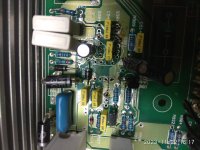
Attachments
Last edited:
if the supply works with light bulb but burns up when connected directly i would look for a fault in the output amplifiers.
Sorry i must clarify that smps(second time repair attempt) was under test WITHOUT any load.Amplifier disconnected!
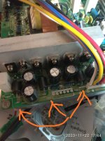
I have also test power amplifier for shorted output power transistors.
I have also test power amplifier for shorted output power transistors.
Sorry,one more time.
SMPS working ok Without load(light bulb connected). This has been tried ,repeating on-off-on many times.
SMPS burn instadly Without load(directly connected to the main).no light bulb.
SMPS working ok Without load(light bulb connected). This has been tried ,repeating on-off-on many times.
SMPS burn instadly Without load(directly connected to the main).no light bulb.
Last edited:
RGT40TS65D better in cin (easy to drive), shorter delay time. lower Vce sat but slightly lower collector currentIf you will find some free time,please can you compare two IGBT,the on in the part list IRG4PC50W AND the second that i used RGT40TS65D.
I think it should works as replacement
Yes the bulb is in series with the primary A.C??
the bulb is in series with the primary AC , no?
ok so it works on the current limiter (bulb)without the load but burns up without bulb in place and under load correct?
to me that still says there's a problem with the load whether it be the output,the low voltage rails there's something going on...
to me that still says there's a problem with the load whether it be the output,the low voltage rails there's something going on...
Last edited:
This is bad news.RGT40TS65D better in cin (easy to drive), shorter delay time. lower Vce sat but slightly lower collector current
I think it should works as replacement
As soon as it should works where is the diabol?🤔
Yes, it is a vexing fault…. The waveforms of post 54 say it all - if the burn up also happens with NO Load. It’s only running around 80% duty cycle, so unless those off times get just stupidly spread out the converter itself will run fine. Not even requiring a resonant mode. Those effects are load dependent.
Whatever the problem, it’s happening right at start up, and the resistance of the bulb limiter mitigated it. If something is happening out of sequence at start up (perhaps forcing both IGBTs on for a few microseconds) it’s going to be very hard to capture. In that case, slowing down the start up is the only way. If the “NTC” has a shorting relay it’s probably really a “PTC” which emulates the light bulb. You may just need more hot resistance to be safe. It sounds like that IR chip was just a bad idea from the start, and that an old TL494 and separate high/low side driver chip - from IR - would have been better.
Another possibility is that the 3.4 uH in the transformer just might not be enough to allow empty capacitors on the secondary side to charge safely the FIRST time. This would also show up at extremely heavy load, as the charging pulses would get to dangerous levels. Normal light loads would run with no problem - AFTER successful start up. This is just a design problem. The solution would be a softER start up, and putting about 20 uH in between the secondary rectifiers and the caps. That will slow the charging down. It’s a LOT easier on the rectifiers and caps too. You lose a little peak power (supply drops a little faster under load) but no RMS power (it drops to the same level at full load, dictated by the duty cycle). That duty cycle looks like about 80% to me - which should allow a sloppy, hard switched circuit to work safely.
Thank you!
Speaking for modifications what's your opinion if i place a small circuit around LM555 to control the relay,given more time delay at start up?
Like in this circuit.
Speaking for modifications what's your opinion if i place a small circuit around LM555 to control the relay,given more time delay at start up?
Like in this circuit.
Attachments
Last edited:
I would limit the peak CURRENT to lower value at start up, rather than just giving it more time.
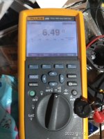
Sorry,thermistor is an NTC type.
Checked.
Cold is 10 ohm.
Lower resistance as go hot.
Another modification...10ohm/5w resistor in series with the thermistor?
Checked.
Cold is 10 ohm.
Lower resistance as go hot.
Another modification...10ohm/5w resistor in series with the thermistor?
Attachments

Last edited:
That is designed to limit the peak off the MAINS for charging the 340V bus so you don’t fuse the switch contacts. That in no way helps with start up surges in the converter, which is what apparently is happening.
Caps are pretty small, and it does use filter inductors so the designers at least thought THAT through properly. If nothing there is fried it shouldn’t have excessive draw off the secondary. I’ve seen them use 4700uf and no inductance save the leakage reactance in the trafo. Ive blown hexfets across the room doing that myself without a ramp-up in the converter duty cycle. Got to be a problem with the switching controller chip section itself.
- Home
- Amplifiers
- Solid State
- PHONIC 740 mixer-amplifier