OK just found them, indeed the same die in a sot89 package. That should work. Make sure the collector pin has a decent thick wire such that it has an additional heatsink to the PCB.
Thank you!
I will order both and i will try to use the sot23 as i see that is designed for the job "The ZXGD3004E6 is a high-speed, non-inverting single gate driver designed for switching MOSFETs or IGBTS."
If this will be very difficult to solder,i will use the SOT89.
I will order both and i will try to use the sot23 as i see that is designed for the job "The ZXGD3004E6 is a high-speed, non-inverting single gate driver designed for switching MOSFETs or IGBTS."
If this will be very difficult to solder,i will use the SOT89.
Last edited:
https://gr.mouser.com/ProductDetail/SparkFun/BOB-00717?qs=WyAARYrbSnbMtAdXyeHyNw==
This adapter will be usefull
This adapter will be usefull
I hope that this will be ok🤔sorry to hear that,; the fast version IGBT is very much needed, don't even try the slow one. can't find the ftx type numbers in the diodes database. fakes again ?
one option to replace the NPN PNP with a sot26 smd from zetex, they have gate drive packages NPN and PNP in one package capable of driving igbt's with 2A peak currents. for example ZXGD3004E6.. made for the heavy lifting..
Attachments
First test is successful!
Thank you basreflex for help.👍
A small video when smps connected in series with a 💡 60W.
Unfortunately server say that is too long.😞
Thank you basreflex for help.👍
A small video when smps connected in series with a 💡 60W.
Unfortunately server say that is too long.😞
Failed again!
After some successful on-off using the bulb tester,i tried to connect everything and power on the unit.
Burned immediately... 😢
I will give it up!
After some successful on-off using the bulb tester,i tried to connect everything and power on the unit.
Burned immediately... 😢
I will give it up!
Hi greenocean,i decided to repair it one last time.
This time i will change all the small caps.
Waiting for parts to arrive i have desoldered C913,C916 among with others.
I have measured all and i can't see any out of specs.
Although this,i will replace all.
Unfortunately my first test was for capacitance only.
Trying to measure for ESR the other day using another measurement tool DER EE5000, i discovered that i lost this 22uf.
I have tried hard to find this but no luck.
You are right about the delay,i have make this circuit on a breadboard to study further.
I have placed the collector of Q908 to the positive supply through a resistor connected in series with a Led and i see clearly the delay.
Please look here post #29 for more details https://www.diyaudio.com/community/threads/help-me-to-find-an-igbt-alternative.405204/page-2
Last edited:
oh sorry I missed post 30, I hope you can fix it soon.
Yes, I also experienced several times SMPS with the IR2153 (DIY) suddenly burned when it was powered on, from there I started to stop using the IR2153 and returned to using the TL494/SG3525.
One thing you might do is try increasing the NTC value, for example using 47 ohm or some lower value in series
What do you think if i will try to remove the relay that is for shorting the NTC?
Just for testing.
Now i know very well that IR2153 is a very stupid i.c.. but it is an existing circuit that i need to repair.
Just for testing.
Now i know very well that IR2153 is a very stupid i.c.. but it is an existing circuit that i need to repair.
Last edited:
"What do you think if i will try to remove the relay that is for shorting the NTC?
Just for testing." I'm afraid it will burn again.
can you measure C922 value and transformer leakage inductance (measure primary inductance with all secondary shorted).
I want to know the resonant frequency (Fr)
in my calculation switching frequency (Fs) will be arround 70-72kHz (with 10K and 1nF)
this smps should run Fs below the Fr (ZCS region)
the schematic is similar to behringer SPS1000, behringer use 2x 22 ohm for inrush current limiting
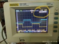
I have measured frecuency when it was working with the in series bulb .
It was 70khz,the same as in the test circuit.
C922=1uf measured out of circuit.
I can measure the transformer leakage inductance this afternoon.
Thank you for the interesting!
It was 70khz,the same as in the test circuit.
C922=1uf measured out of circuit.
I can measure the transformer leakage inductance this afternoon.
Thank you for the interesting!
Attachments
Last edited:
it looks normal with 3uH and 1uF then the resonant frequency is 91kHz.
Indeed, the main problem with the IR2153 is that it does not have a softstart function
Indeed, the main problem with the IR2153 is that it does not have a softstart function
have you considered the option of replacing the controller with another one, sg3525 for example? by using a small PCB on top of the main PCB
Thanks.
Can you calculate again using 3.4uH and 1uf?
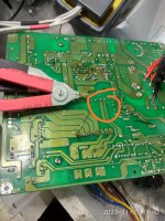
I asked because i have short a coil that is in the primary side too.
Ieaving this open the measured value is 3.4uH.
I don't know if you have noticed that this repaired smps connected in series with a bulb tester working well and the measured frequency is 70 khz.
Unfortunately the option you asked about is out of my knowledge 😕
Can you calculate again using 3.4uH and 1uf?
I asked because i have short a coil that is in the primary side too.
Ieaving this open the measured value is 3.4uH.
I don't know if you have noticed that this repaired smps connected in series with a bulb tester working well and the measured frequency is 70 khz.
Unfortunately the option you asked about is out of my knowledge 😕
Attachments
Last edited:
it's around 86kHz https://goodcalculators.com/resonant-frequency-calculator/
yes I noticed it. after successfully start with light bulb it will be fine, but without it maybe next day, next month... it will burned at startup.
also NTC needs time to cooldown to reset it's value, rapid on off will burn IGBT
this is LC series resonant converter working in ZCS region (Fs below Fr)
if we shift resonant frequency higher then peak current at startup will be lower. but maximum peak power will be reduced
this is the startup current flowing through C922 (1uf and 3.4uH). please notice that the power source in simulation is ideal

I change C22 to 560nF (Fr = 115kHz), startup current reduced

what I can suggest is:
1. Try to increase NTC value, ex. 47D15
2. Try to reduce C22 ex. 560nF (resonant capacitor) to shift resonant frequency up
3. put your light bulb in place of NTC if there is enough space. it's crazy but it works
4. replace controller, maybe I can help (design) but it may take a few days
Did I miss that you checked the secondary and everything is fine?
I am sorry maybe my knowledge is not enough to solve your problem
yes I noticed it. after successfully start with light bulb it will be fine, but without it maybe next day, next month... it will burned at startup.
also NTC needs time to cooldown to reset it's value, rapid on off will burn IGBT
this is LC series resonant converter working in ZCS region (Fs below Fr)
if we shift resonant frequency higher then peak current at startup will be lower. but maximum peak power will be reduced
this is the startup current flowing through C922 (1uf and 3.4uH). please notice that the power source in simulation is ideal
I change C22 to 560nF (Fr = 115kHz), startup current reduced
what I can suggest is:
1. Try to increase NTC value, ex. 47D15
2. Try to reduce C22 ex. 560nF (resonant capacitor) to shift resonant frequency up
3. put your light bulb in place of NTC if there is enough space. it's crazy but it works
4. replace controller, maybe I can help (design) but it may take a few days
Did I miss that you checked the secondary and everything is fine?
I am sorry maybe my knowledge is not enough to solve your problem
- Home
- Amplifiers
- Solid State
- PHONIC 740 mixer-amplifier