And here is an interesting Pettals result for a FFFF acrylic panel, using the default values for acrylic, including a Q of 10.
The sensitivity is really low, as expected with acrylic, but the predicted response is remarkably flat. I found a panel of these dimension online for under $20, so I will see how it really performs when that arrives!
Eric

The sensitivity is really low, as expected with acrylic, but the predicted response is remarkably flat. I found a panel of these dimension online for under $20, so I will see how it really performs when that arrives!
Eric
Eucy,I don't think a CF/balsa sambo is going to be 2
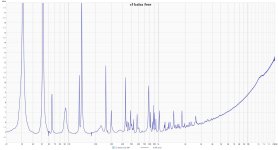
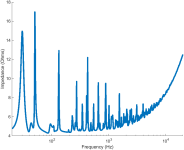
Here (below left) is the impedance curve I measured using REW for a "free" CF/balsa sandwich panel, with a 25VT-4 exciter, Below right is the Pettals FFFF sim using Q=100. Obviously they are not a perfct match, but they are at least qualitatively similar. It should be noted too that the actual CF/balsa sandwich panel is not isotropic, and the real panel isn't truly "free" but hanging from two wires. So it's unreasonable to expect a perfect match. Also, in real life, Q is likely a function of frequency. But that said, I think it's reasonable to say that the "intrinsic Q" of this panel is pretty darn high, and likely in the ballbark of 100.


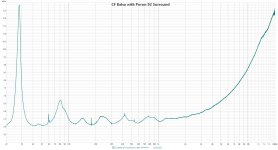
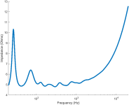
And here (below left) is the impedance curve I measured for the same (or similar) CF/balsa panel mounted to a frame with Poron foam, and also with a 25VT-4 exciter. On the right is the Pettals SSSS sim for Q=3. Again, it's not a perfect match, but I think it's fair to infer that the result of the Poron foam perimeter is a "system Q" of on the order of 3, even if the panel itself is closer to Q=100. (The tiny sharp spikes in the REW measurement here should be ignored, they are system noise).


Eric
Yes, I have given it a go, but I am a bit embarrassed to share my sims and REW measurements since I’m not sure that I understand what I am doing in either PETTaLS or REW. What I have played around with so far is to build a canvas framed panel as described in post #93, which also shows the simulation. Dave actually did another (more accurate?) simulation in Post #96 using a 32mm exciter.Have you given Pettals a try? If not, give it a go and maybe even share a Pettals result that looks good to you.
I have used a XT32-4 exciter and actually mounted the exciter at another/better position using REW’s RTA function.
Here are the REW measurements I made at 1m for my small A4 framed canvas acrylic panel:
Looks like Mount Everest.
Here zoomed out with 1/6 smoothing:
Not sure if this is good or bad, but the (single) panel does not sound too bad. Compared to a free hanging 2mm poplar plywood panel the plywood sounds better to my ears. I have not made any progress on this project yet. My next plan is to make another A4 canvas framed panel, but with 2mm poplar plywood and compare to the acrylic one.
Oh yeah, now I remember that. I think the real challenge in your case, as Dave pointed out, is that the "canvas framed" mouting is likely somewhere between FFFF and SSSS. But the two are so different, that I have no idea how to somehow intopolate between them to get anything really useful from the model. That's my take, anyway.What I have played around with so far is to build a canvas framed panel as described in post #93, which also shows the simulation.
But don't let that stop you from playing with Pettals and posting sims.
Eric
I just ran into this thread for the first time. Really interesting, and think it would be a great move forward should this simulation method prove accurate.
Has anyone looked into properties of 3D-printed materials such as ASA-cf (very light weight and stiff) and TPU (heavier and flexy)?
Has anyone looked into properties of 3D-printed materials such as ASA-cf (very light weight and stiff) and TPU (heavier and flexy)?
I don't think that P****s is quite ready for design use. I have played around with aspect ratios and found that for a 300 width panel, the optimum height seems to be 700.I'm disappointed that nobody has shared their own Pettals designs yet.
Eric
I have concerns over the mid to hf response graphs in that they all look way too flat...ie, the roll-off doesn't match our experiences.
On the topic of damping...I'm thinking there's a strong case for testing spray on damping material...I just haven't had time
Eucy
You may be right, of course. But even so, I think there may be value in playing with it. Even if there are aspects that don't match, our experience.I don't think that P****s is quite ready for design use. I have played around with aspect ratios and found that for a 300 width panel, the optimum height seems to be 700.
I'll be interested to see what you find with spray on damping materials when you get to it.
Eric
They're remarkably close Eric.. Well tested!!Eucy,
Here (below left) is the impedance curve I measured using REW for a "free" CF/balsa sandwich panel, with a 25VT-4 exciter, Below right is the Pettals FFFF sim using Q=100. Obviously they are not a perfct match, but they are at least qualitatively similar. It should be noted too that the actual CF/balsa sandwich panel is not isotropic, and the real panel isn't truly "free" but hanging from two wires. So it's unreasonable to expect a perfect match. Also, in real life, Q is likely a function of frequency. But that said, I think it's reasonable to say that the "intrinsic Q" of this panel is pretty darn high, and likely in the ballbark of 100.
View attachment 1452433 View attachment 1452434
And here (below left) is the impedance curve I measured for the same (or similar) CF/balsa panel mounted to a frame with Poron foam, and also with a 25VT-4 exciter. On the right is the Pettals SSSS sim for Q=3. Again, it's not a perfect match, but I think it's fair to infer that the result of the Poron foam perimeter is a "system Q" of on the order of 3, even if the panel itself is closer to Q=100. (The tiny sharp spikes in the REW measurement here should be ignored, they are system noise).
View attachment 1452435 View attachment 1452436
Eric
Eucy
Hi ChristianThank you Eric. Yes it is a satisfaction to have this FDM script running. It should allow to test different mounting solutions and it is ready to give results for orthotropic materials... at the condition to be able to feed it some material characteristics and to be able to evaluate the results.
An other interest is the possibility to loop over a set of characteristics, letting the computer working for example at night and then collecting the results. The condition for that is to define criteria which seems possible (ie the smothness of the FR on a certain frequency range).
The main question in front of us is how it is representative... We have 2 possible observable physical quantities which are the impedance and the response of an open back panel. We already know from Dave there are difference between the simulation in PETTaLS and the measurement of the impedance. I have the feeling that has important consequences : first about the model (need of improvement?), second on the SPL simulation as the impedance plays a role in it (at least in my script). For the SPL of an open back panel, for now it is not an output of a simulator. There is here an additional modelling effort needed... hoping it is possible.
@EarthTonesElectronics
Dave, if you have suggestions of an algorithm to get the SPL of an open back panel, please, let me know.
Christian
PS : other advantage of the FDM, is the possibility to simulate easily adding mass like the one we see on the commercial DML either to balance the panel or to tam some modes
I've been doing some research on this and it seems very difficult to get accurate results for high frequencies with most/all approaches
What have you found that will work up to 20k?
Eucy
Hi Eric -I thought it might be interesting to talk about what the results of a "good" DML design might actually look like in Pettals.
So I am inviting those who are interested to come up with a virtual design that looks good to you, and share it with the rest of us. The idea for the time being is to simply assume that Pettals is perfectly accurate, and find and share a design and response in Pettals that looks like the response you would like to see from your own DML panel. Use whatever material properties and configuration that you want.
The design/response below is my first entry. In the interest of being realistic (or close), I tried to limit myself to:
My design goals were:
- Designs using one of the three actual exciters in the program (i.e. not point force)
- Material properties that are (hopefully) within the realm of possibility.
- SSSS panel (I'll try FFFF next).
Feel free to make up your own constraints and goals.
- Sensitivity >90 dB at 1 watt
- Flat-ish response over the widest frequency range possible, with emphasis on 100 Hz to 10 kHz
- Slight downward slope okay/preferred.
- Minimal variation of FR with angle, directivity always positive, or nearly so.
- Clean impulse response without long tails.
Below is what I came up with, the second screenshot is the same as the first, but with the impulse response plot selected instead of the Polar response.
View attachment 1451785 View attachment 1451792
Some points:
Next I'll try an FFFF design. Meanwhile, I'm interested to see what looks good to you guys.
- The panel properties are approximately what I get with a carbon fiber balsa sandwich, but for this design I need balsa and cf fabric about half the thickness of what I have made before.
- I chose a thickness that put the coincidence frequency and exciter cut-off frequency at the same value. However, since the panel is not isotropic the prediction of fc is dubious.
- The panel size was made just large enough to get the fundamental frequency (first impedance peak) at around 100 Hz.
- The aspect ratio and exciter location were positioned by trial and error to get the flattest possible response.
- I used a Q of 2. I'm not really sure if it is really possible to get Q quite that low. Using Poron foam on the perimeter with the thicker versions of these panels resulted in a Q of near 3, I think. I don't know if Q will be higher or lower with a thinner panel. Using Q=1 gives an even flatter response, with virtually no cost in output, but setting Q any lower than 1.0 starts hurting output SPL.
- Probably the weakest part of the response is around 1000 Hz, were there is a bit of a dip in the on-axis response, and the DI goes slightly negative, but otherwise I think the simulation looks pretty good.
Eric
Wow, I'm really falling behind on the forum. Sorry!
There are so many possible design goals for DMLs, and I'm going to propose a completely different design goal than the one that you had proposed. While I think aiming for a low-Q speaker will definitely sound good, it more or less mirrors the ideal behavior of a traditional cone loudspeaker and, in my opinion, doesn't take full advantage of the panel.
After working towards that goal for years, I'm recently finding large speakers with intentionally erratic directionality to be really interesting (I also like playing around with prescribed directionality, e.g. beamforming).
I designed (in PETTaLS) a 0.7mm FFFF glass speaker with corner supports, 0.8m x 0.27m, with a single small Tectonic exciter such that the coincidence frequency and driver critical frequency (still not sure what to call it) overlap at roughly 16 kHz and don't affect the audio frequency range too much. By the way, I'm cheating and using the PETTaLS version with extra options.
Here's the polar response and frequency response.
Here are the surface velocity shapes and radiation patterns (I like the erratic responses above 1 kHz). These shapes are actually from a speaker with a slightly different aspect ratio, but it illustrates the point and I didn't feel like going through the hassle of taking a bunch of screenshots again!
This speaker has a more-or-less flat response, besides some peaks and dips below 200 Hz. It's pretty omnidirectional at all frequencies too, or at least after you realize that the erratic directionality shifts don't lead to any enormous dark spots in the polar response.
I think this is probably due to the discretization of the exciter ring shape, which always comes out a little bit lopsided. I haven't seen the effects so dramatically before, though, so I'll look into it more!@EarthTonesElectronics
Dave,
I just tried this sim of an FFFF plate with the exciter in the center of the X direction. I was surprised to see that the responses at +90 and -90 are pretty different, particularly in the region of 150 Hz to 2000 Hz. Interestingly, in that same frequency region, the surface velocity maps look very symetric, like the one shown at 757 Hz. I have not see anything like this with SSSS conditions.
Any thoughts?
Eric
View attachment 1451802
Dave, Welcome back!There are so many possible design goals for DMLs, and I'm going to propose a completely different design goal than the one that you had proposed. While I think aiming for a low-Q speaker will definitely sound good, it more or less mirrors the ideal behavior of a traditional cone loudspeaker and, in my opinion, doesn't take full advantage of the panel.
Of course, this is exactly the kind of discussion I hoped to generate, and a great thing about having Pettals is that it provides a means of "describing" a particular kind response in a far more objective way than we can without it.
Concerning the design you shared, I have to wonder whether or not it is really that different from the low Q SSSS design that I shared initially. That is to say, when the variations in directivity are at such a fine level, can our brains tell the difference between the two responses below? Ignoring of course the obvious difference in sound volume, and directivity above 10 kHz. Or are the differences smoothed out somewhere in the process? I'm not claiming to know, but I do wonder.
I designed (in PETTaLS) a 0.7mm FFFF glass speaker with corner supports, 0.8m x 0.27m, with a single small Tectonic exciter such that the coincidence frequency and driver critical frequency (still not sure what to call it) overlap at roughly 16 kHz and don't affect the audio frequency range too much.
As you may have noticed, I am leaning toward the same approach, that is, designing such that the coincidence frequency (red line) and critical frequency (blue line) coincide. Perhaps that was an approach you mentioned in one of the videos, but I don't recall.
What took me a while to realize, however, is that for a given driver, that frequency is the same no matter what the panel material is. That is, if I pick a particular driver and particular panel material, then tweak the panel thickness to make the coincidence and critical frequencies land on top of each other, they converge at the same exact frequency no matter what the panel material is.
After noticing this "empirically" (i.e. playing around with Pettals), I did the algebra and realized that the formula for that frequency is remarkably simple:
fcc=c/(r*8.02^0.5)
where:
fcc="critical coincidence frequency"
c=speed of sound
r=exciter ring radius
8.02=thin ring exciter cutoff factor (from your recent paper).
Probably you know this, but maybe others don't.
Eric
OMG I just realized just how big and thin that really is! I was going to ask how many of them you have broken so far and realized that you probably havent broken any, since it's only virtual design, so far, yes?I designed (in PETTaLS) a 0.7mm FFFF glass speaker with corner supports, 0.8m x 0.27m, with a single small Tectonic exciter such that the coincidence frequency and driver critical frequency (still not sure what to call it) overlap at roughly 16 kHz and don't affect the audio frequency range too much.
Eric
Interesting, but why glass? What properties of glass (as opposed to say acrylic) makes it good for DML?a 0.7mm FFFF glass speaker with corner supports
But this surely only holds for iso materials. The wave speeds in anisotropic materials vary with directional stiffnesses, so how is that handled?As you may have noticed, I am leaning toward the same approach, that is, designing such that the coincidence frequency (red line) and critical frequency (blue line) coincide.
I recall( I think) Dave saying PeTTALS assumes the X and Y coincidence frequencies to be the same, but they're not... Or do I remember incorrectly?
Eucy
Further note to the above. At 20k, the bending wavelength can be of the order of 10-20mm, so for decent resolution in FDM, readings tell me we need grid spacings of less than 1/6th of the wavelength, ie 2 to 3mm... Thousands of nodes...Not practical for DIY computers...Hi Christian
I've been doing some research on this and it seems very difficult to get accurate results for high frequencies with most/all approaches
What have you found that will work up to 20k?
Eucy
Even standard FEM methods have the same problems.
I'll have to go back and see what PeTTaLS is based on and how this is overcome.... Maybe it explains why the PeTTaLS hf region plots are flatter than what we get in testing?? Dave???
Eucy
Eucy,But this surely only holds for iso materials. The wave speeds in anisotropic materials vary with directional stiffnesses, so how is that handled?
I recall( I think) Dave saying PeTTALS assumes the X and Y coincidence frequencies to be the same, but they're not... Or do I remember incorrectly?
Yeah, that's right. Iso only. I don't think that even the premium version of Pettals can handle orthotropic materials.
For isotropic materials the X and Y coincidence frequencies are the same, but not for orthotropic.
Eric
Hello Eucy,What have you found that will work up to 20k?
It is not in my current target to simulate up to 20k. The first reason is that I am afraid it is difficult to model the behavior of the different materials up to that. The second is that above maybe 5k I think there are less parameters leading the design than below. I mean it is a mainly matter of material and exciter but not of geometry (suspension, damping, additional mass, etc).
I think that all the method based on a mesh like FDM, FEM have a limitation in high frequency. The mesh needs to be smaller than the shortest wave length. It is a matter of computation time.
Recently I found a paper about a method that doesn't have this limitation. It is based on image sources as in room acoustic simulation. From a first reading of this paper, the math was above my head!
Christian
In my understanding, PETaLLS is based on the mode decomposition. The mode shape are calculated from the formulas coming from the work of M Warburton which opened the way to estimate the modes for any combination of standard edge conditions (free, simply supported, clamped) . I don't understand currently how it can be extended to "exotic" suspension methods bit it seems Dave found a way to do it!I'll have to go back and see what PeTTaLS is based on and how this is overcome.... Maybe it explains why the PeTTaLS hf region plots are flatter than what we get in testing?? Dave???
Christian
- Home
- Loudspeakers
- Full Range
- PETTaLS Flat Panel Speaker Simulation Software