Hello Christian
What were the edge constraint conditions of the panels you did the directivity tests on... And were that all consistent?
Eucy
What were the edge constraint conditions of the panels you did the directivity tests on... And were that all consistent?
Eucy
@EarthTonesElectronics
Dave,
I still suspect my computer might not really be up to the task, but I'm wondering why Pettals seems to be using som much memory and CPU and while nothing is apparently happening. Here I had asked for a new sweep to start but there was no indication on the screen that it was even running. When this happens sometime I just shut down and restart my computer and it runs a few sims until the same thing happens, i.e. nothing apparent happening but lots of memory and CPU in use.
Eric
@EarthTonesElectronics
Dave,
I just observed something that seems odd to me. The simulation is of a highly damped FFFF plate, otherwise using properties roughly like a fiberglass/balsa sandwich panel I made. The thing that seems odd to me is that the impulse response is showing a strong resonance at around 156 Hz, and there is a corresponding peak in the impedance at nearly the same frequency, which is typical. But those peaks coincides with a very strong dip in the SPL at the same place. Does it make sense that there really could be such a strong ridge in the impulse response at the same frequency as the deep dip in the frequency response?
Eric
Hello Eucy,Hello Christian
What were the edge constraint conditions of the panels you did the directivity tests on... And were that all consistent?
Eucy
Most of my directivity tests were done with a panel suspended by the middle of its top short side. The exception is the PMMA panel (the one I called PS1!) which had a full peripheral suspension made of EPDM D shape seal.
I have not seen for now an impact of the edge constraint on the directivity... but I was more focused on the detection of the coincidence frequency and the additional SPL from the back side.
Christian

I think the colors and the low resolution at these low frequencies can be a little misleading. If you rotate the IR plot so that it looks more like a waterfall you can tell what's going on a little better.@EarthTonesElectronics
Dave,
I just observed something that seems odd to me. The simulation is of a highly damped FFFF plate, otherwise using properties roughly like a fiberglass/balsa sandwich panel I made. The thing that seems odd to me is that the impulse response is showing a strong resonance at around 156 Hz, and there is a corresponding peak in the impedance at nearly the same frequency, which is typical. But those peaks coincides with a very strong dip in the SPL at the same place. Does it make sense that there really could be such a strong ridge in the impulse response at the same frequency as the deep dip in the frequency response?
Eric
View attachment 1442446 View attachment 1442449
It looks to me like there are three ringing frequencies that correspond to the "peaks" between the sharp nulls. The specific ringing that you were pointing out seems to come from the pseudo-peak around 120 Hz. The colors are assigned based on the value at the lower frequency for each mesh surface, so it makes it look like the red color is assigned to a higher frequency than it actually is with this low of resolution.
I'm not totally sure. I can say, though, that I'm not having this problem on any of the computers I've been running my program on. Matlab is a compile-at-runtime language, though, so the execution performance depends a lot on the specific machine.@EarthTonesElectronics
Dave,
I still suspect my computer might not really be up to the task, but I'm wondering why Pettals seems to be using som much memory and CPU and while nothing is apparently happening. Here I had asked for a new sweep to start but there was no indication on the screen that it was even running. When this happens sometime I just shut down and restart my computer and it runs a few sims until the same thing happens, i.e. nothing apparent happening but lots of memory and CPU in use.
Eric
View attachment 1442060
There's a couple things I can do to probably free up some memory (I would maybe also guess that your CPU shows such high usage because it's keeping a lot of values in cache, but I'm not totally sure). The IR spectrogram can be resampled to take up less memory, and based on some code rewrites I don't need to store the surface velocity at every frequency any more, so let's see if that helps!
Dave,
Sorry if you responded to this suggestion before, but are you thinking of having a means to save records? Either of the simply sets of conditions, or full sim results? It would be nice to have a way to save simulations that are particularly good or interesting for one reason or another.
For the impulse response, it seems like it would be nice to have it reoriented (frequency horizontal), and lined up with the frequency response just like the spinorama is now. I know there is not really enough room for all three, but maybe you could set it up so that you could swap back and forth between the spinorama and the impulse response. Just a thought.
Eric
Uploaded a new version (1.4.2) with a bunch of the features suggested over the previous week or two. This is one of them - the polar response (spinorama) and IR are both above the FR, on different tabs.For the impulse response, it seems like it would be nice to have it reoriented (frequency horizontal), and lined up with the frequency response just like the spinorama is now. I know there is not really enough room for all three, but maybe you could set it up so that you could swap back and forth between the spinorama and the impulse response. Just a thought.
The link again, just in case anyone's having trouble finding it: https://github.com/daveanderson130/PETTaLS-Free/releases/tag/v1.4.2
Also working on some new videos, including videos of the advanced version with multiple exciters and fancy boundary conditions! Those will start coming up within a few days and I'll post links to those as well.
It seems the Linux version is still in the owen? ;-)Uploaded a new version (1.4.2) with a bunch of the features suggested over the previous week or two.
Christian
It's up there now!It seems the Linux version is still in the owen? ;-)
I want to make sure that I spend a while testing the Windows version before I go through the process of compiling the Linux version, but it seems like it all checks out. One weird thing, though, is that the FR lines on the Linux version are coming out a different color than on the Windows version.
I just loaded the new Windows version. I only ran the default sim so far, but I like the layout!
Eric
Eric
Dave,
I've been playing around and the new version seems a little faster. Also, I'm looking more at the velocity plot more than I did before, The plots come up faster than before, so now it's less risky to look at one. It's interesting how adding damping really reduces the panel velocity curve, but doesn't reduce the SPL. Does that make sense to you?
You mentioned before that you are really interested in the velocity profile, why is that and what do you look for?
Some minor suggestions:
When you have "compare" checked the old velocity profiles remain but not the impedance curves. Maybe they both should remain (by default if compare is checked) but have a "refresh" button to get rid of the old ones when the plots get cluttered. On the freq response plot you can "refresh" just by unchecking compare, then selecting a different angle choice from the drop down, but that doesn't work for the other plots.
The drop down arrows for the freq response plot and smoothing shouldn't be so far over to the right. The arrows should be only as far right as the graph border, I would say.
Eric
@EarthTonesElectronics
Hi Dave - Can you please check and advise why the sim shown shows a much poorer response graph from the 32mm thruster vs the 25mm VT-4.
The 32mm unit has a slightly higher BL than the 25VT-4, and Dayton's FR graphs show the thruster giving about 7dB more than the 25mm unit at 100-200Hz (On foamcore) vs the sim, which is about 10dB lower for the 32 than the 25.
Also there's a marked difference in the lack of roll-off at HF's in the sim vs the Dayton graphs for both exciters. Blue=25VT-4, red=32EP-4

Thanks
Eucy
Hi Dave - Can you please check and advise why the sim shown shows a much poorer response graph from the 32mm thruster vs the 25mm VT-4.
The 32mm unit has a slightly higher BL than the 25VT-4, and Dayton's FR graphs show the thruster giving about 7dB more than the 25mm unit at 100-200Hz (On foamcore) vs the sim, which is about 10dB lower for the 32 than the 25.
Also there's a marked difference in the lack of roll-off at HF's in the sim vs the Dayton graphs for both exciters. Blue=25VT-4, red=32EP-4
Thanks
Eucy
Attachments
There are at least 2 things going on here...Hi Dave - Can you please check and advise why the sim shown shows a much poorer response graph from the 32mm thruster vs the 25mm VT-4.
The 32mm unit has a slightly higher BL than the 25VT-4, and Dayton's FR graphs show the thruster giving about 7dB more than the 25mm unit at 100-200Hz (On foamcore) vs the sim, which is about 10dB lower for the 32 than the 25.
1. In our tests, the EP-4 actually did have a lower BL than the VT-4. We've also seen, though, that the tolerance is huge on these billionsound exciters, probably up to as much as 50%. If we had more funding to test a wide range of units we could come up with a better estimate of where the middle of the bell curve was for each exciter model, but alas, we don't right now! That being said, the EP-4 is still capable of making a louder speaker because it can handle double the wattage of the VT-4.
2. There's also the issue of impedance matching - At 100 Hz, 1/2" EPS is very floppy, and the exciter doesn't have to push against. The 32EP-4 is a much stiffer exciter than the 25VT-4, so the relative squishiness of the 25VT-4 is actually better impedance matched to the floppiness of the EPS.
Thanks Dave, those of us who have used the Thruster have generally not been impressed, but 50% tolerance on BL we wouldn't be expecting...
That's terrible quality control.
What about the hf roll-off differences?
Eucy
That's terrible quality control.
What about the hf roll-off differences?
Eucy
Hi again Dave.
In asking about the Sims extended hf response, I'm mindful of the forum member's general experience that EPS has a relatively poor response above about 10k. I presume you would have many test results vs sims for EPS ??
Eucy
In asking about the Sims extended hf response, I'm mindful of the forum member's general experience that EPS has a relatively poor response above about 10k. I presume you would have many test results vs sims for EPS ??
Eucy
My friend Steve wrote quite a bit about this in his PhD thesis. They're cheap exciters, though, so you get what you pay for!That's terrible quality control.
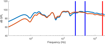
At first I thought this would be due to the voice coil impedance, but after checking my measurements those two exciters have relatively similar impedance curves at high frequencies. This means, then, that the HF roll-off would be due to the larger ring shape of the EP-4. I ran a simulation using 6mm thick aluminum, which has wavelengths larger than both exciters even at 20kHz, and there's no real roll-off difference between the exciters (orange is VT-4, blue is EP-4):What about the hf roll-off differences?
Not yet, actually - but I've got a bunch of EPS panels that I'm planning to test as soon as I can get around to it! (I work on a lot of other research as well, and the other projects have been picking up quite a bit lately)I presume you would have many test results vs sims for EPS ??
Link to the full document : Non-linear characteristics and subjective listening studies of flat-panel loudspeakersMy friend Steve wrote quite a bit about this in his PhD thesis.
Thanks Dave. This means, then, that the HF roll-off would be due to the larger ring shape of the EP-4.
I was really getting at the fact that the Sim roll-off of both is less than we typically get in practice. Our general conclusion is (I believe) that with EPS it's most likely due to through-thickness shear deformation, a feature which would not be picked up by thin plate theory.
A secondary cause applicable to all panel materials (but perversely, probably less so with EPS) may be voice coil deformation ala Zenker.
Eucy
@EarthTonesElectronics
Hi again Dave,
The obvious questions I failed to ask previously:
Have you measured the BL figures for the 25 and 32 mm exciters used as standards in PeTTALS, and do they match the Dayton figures.?..If so then the output of each at lower frequencies should be closer?, and if not then maybe we need the figures you achieved so we are comparing apples with apples.
Cheers
Eucy
- Home
- Loudspeakers
- Full Range
- PETTaLS Flat Panel Speaker Simulation Software