So i have decided to make a version 2.0 with two transistor pair. Will trace my own PCB. Planning on making the output transistors not under the PCB, make more place for bigger caps on board, and not use those PCB studs for fast connecting. Use a screw terminals instead. So the small footprint is not a priority, yet making as small as possible. Thanks for design. I guess i wont need to change any values after so many have tried the design already 🙂
So i have decided to make a version 2.0 with two transistor pair. Will trace my own PCB. Planning on making the output transistors not under the PCB, make more place for bigger caps on board, and not use those PCB studs for fast connecting. Use a screw terminals instead. So the small footprint is not a priority, yet making as small as possible. Thanks for design. I guess i wont need to change any values after so many have tried the design already 🙂
Hey that's cool! Looking forward to your take on PeeCeeBee!
 🙂
🙂Hello, Guys.
I've been assembling and testing a V3. initially, I got very good on THD and IMD, however, I noticed that I got better results due to a mistake on assembling. I put a 1 ohm instead of 10 ohms on the V3 Zobel network. my guess is that the oscillation on my V3 is giving bad THD and IMD numbers.
So I'd like to hear experiences on ways to mitigate oscillation on V3.
Could the cap in front of the BCs cause oscillation? some amps have another resistor between the cap and the BCs.
should I increase or remove the cap on the base of the BDs/MJE? some amps have much higher values.
My goal is to have a V3 running without a Zobel with no oscillation, then after putting the Zobel back just to be safe.
Thanks
hello
yesterday, i did some tests on my v3 removing the cap on the input and the zobel resistor. the amp is stable however the distortion on higher frequencies like 3k,5khz are horrible ( 0.15% ).
looks like the v3 needs the zobel to reduce the ringing.
and it isn't very good with lower impedances like 4ohms.
anyone has a sugestion?
did anyone measure the peeceebee with low impedance loads ?
Hello, Guys.
I've been assembling and testing a V3. initially, I got very good on THD and IMD, however, I noticed that I got better results due to a mistake on assembling. I put a 1 ohm instead of 10 ohms on the V3 Zobel network. my guess is that the oscillation on my V3 is giving bad THD and IMD numbers.
So I'd like to hear experiences on ways to mitigate oscillation on V3.
Could the cap in front of the BCs cause oscillation? some amps have another resistor between the cap and the BCs.
should I increase or remove the cap on the base of the BDs/MJE? some amps have much higher values.
My goal is to have a V3 running without a Zobel with no oscillation, then after putting the Zobel back just to be safe.
Thanks
Hi Bruno.
Is the heatsink connected to PSU ground? With well shielded input cables, grounded heatsink and all 100uF + 100pF + 22pF capacitors installed you can run V3 without Zobel. What THD did you measure with 10R Zobel resistor?
hello
yesterday, i did some tests on my v3 removing the cap on the input and the zobel resistor. the amp is stable however the distortion on higher frequencies like 3k,5khz are horrible ( 0.15% ).
This is very dangerous, I hope the amp doesn't get burned. The 100pF capacitor is essential at input as it shunts any RF signal at input which might trigger spurious oscillation in the amplifier resulting into either overheating or extremely bad signal performance.
looks like the v3 needs the zobel to reduce the ringing.
and it isn't very good with lower impedances like 4ohms.
anyone has a sugestion?
did anyone measure the peeceebee with low impedance loads ?
With proper setup with default components V3 won't oscillate. 4R performance is always worse than 8R performance in any amplifier however before considering THD performance please make sure the amplifier is properly trimmed and set-up with all default components installed (including the default 10R resistor in the Zobel). If possible upload a couple pictures. It would make debugging easier for everyone.
Thanks Shaan.
what is the recommended wiring for the input gnd?
yesIs the heatsink connected to PSU ground?
all my good mesurements were with a 1R Zobel.With well shielded input cables, grounded heatsink and all 100uF + 100pF + 22pF capacitors installed you can run V3 without Zobel.
What THD did you measure with 10R Zobel resistor?
what is the recommended wiring for the input gnd?
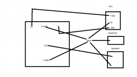
The two ground connections (one between + and - supply headers and one near input side) both connect to PSU ground.
Input cable's shield connects to IN--, core connects to IN++.
Input cable's shield connects to IN--, core connects to IN++.
The two ground connections (one between + and - supply headers and one near input side) both connect to PSU ground.
Input cable's shield connects to IN--, core connects to IN++.
Thanks for your patient, and how about the speaker gnd at the same level too?
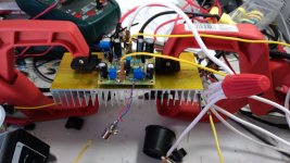
Hello, that's a pic of my PCB v3 on my test bench.
and a pic of the wiring diagram ( this wiring diagram cause the v3 to oscillate ).
Thanks
and a pic of the wiring diagram ( this wiring diagram cause the v3 to oscillate ).
Thanks
Attachments
Last edited:
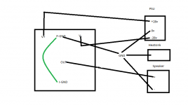
Good to have a star ground. However, the speaker's return (-) is better routed right at the PSU board, not to the star. Can you try it and report?
Thanks for the picture.
Edit: what is the voltage rating of the two 22pF?
Thanks for the picture.
Edit: what is the voltage rating of the two 22pF?
Good to have a star ground. However, the speaker's return (-) is better routed right at the PSU board, not to the star. Can you try it and report?
Thanks for the picture.
Edit: what is the voltage rating of the two 22pF?
I tried the speaker return into the PSU. it still oscillates.
the 22pf cap is 100v.
Thanks Shaan.
Do you hear anything from speaker? Did you measure oscillation frequency? Are the MOSFETs getting hot?
Edit: What value are VAS and MOSFETs biased at?
Edit: What value are VAS and MOSFETs biased at?
Last edited:
Do you hear anything from speaker? Did you measure oscillation frequency? Are the MOSFETs getting hot?
Edit: What value are VAS and MOSFETs biased at?
What I meant by speaker is a 4ohms resistor. no I didn't measure the oscillation because the amp starts to drain a lot of current .. like 750ma per side. yes the mosfets gets hot .
the vas are biased at 10ma and mosfets 50ma.
Last edited:
Can you try this?
Replace 1R zobel with 10R. Remove the 4R resistor (load). Open all connections from the hanging star ground and route all ground wires directly to PSU board's ground with as short wires as possible (including heatsink ground). Turn on amplifier and see if the MOSFETs still draw lot of current. Turn it off. Connect 4R(load). Turn on and see for the same.
Replace 1R zobel with 10R. Remove the 4R resistor (load). Open all connections from the hanging star ground and route all ground wires directly to PSU board's ground with as short wires as possible (including heatsink ground). Turn on amplifier and see if the MOSFETs still draw lot of current. Turn it off. Connect 4R(load). Turn on and see for the same.
Can you try this?
Replace 1R zobel with 10R. Remove the 4R resistor (load). Open all connections from the hanging star ground and route all ground wires directly to PSU board's ground with as short wires as possible (including heatsink ground). Turn on amplifier and see if the MOSFETs still draw lot of current. Turn it off. Connect 4R(load). Turn on and see for the same.
the v3 I'm testing is using a 10R on the Zobel. the only difference is it has a trimmer instead of the diodes to bias the mosfets.
OK, I will try to re-wire all to the PSU and short the GND wire.
Hello,
just trying to get my Peeceebees v4 to run, so here are some questions, since the first steps of the VAS biasing dont seem to work for me:
It states that the initial Vas bias current should be, way less than 10mA, since the reading of the 47R should be around 50mV if i got that right?
My whole current drawn right now on a swtiching +-15V power supply is right now +360mA and negative maybe the same , I did not measure that one directly, but I can tell from the VAs resistors and some other heatings that the current is exceedingdly high.
So I started the whole troubleshooting process 🙂
I will only tell you the reading for the positive Supply rail, the negative ones are slightly worse, so even more current is consumend there, and together with you guys we need to find out wheather some transistor is broken, or something else is wrong, or on the occasino everything is indeed working fine, and i am just doing something wrong.
current into the +Vcc: 0,360mA
voltage on R9 = 10R = 2,6V so 260 mA there;
current into Q9, measurned over R29: V = 4,7V; i=100 mA
both signal or constant current Leds, only slightly lid, which could be perfectly fine, i dont kmnow yet.
So in my opinion the power ratings of those resistors are exceeded, that is why I assume something is wrong.
Some other measuring points:
Input voltae is left floating: voltage reading between R1 and R2, at the signal entry point: 1,6V; strange thing here, this voltage doesnt change when I short the signal input to GND, so my best guess is, this must come from the input transistor pair somehow.
voltage on the collector of Q1, the positive input bipolar: 2,62 V, which I think should be around +Vcc, if I get the circuit right, since the input transistor Q1 should not do anything, right?
I will spent the half day today troubleshooting it, luckily I got another PCB, but the other one seemed even wors, more current drawn.
Maybe I did something terribly wrong with the transistors, but I at least assume and doublechecked if i got the big ones right, amyeb some of the little ones get me screwed.
anyone got some voltage readings etc will help me find my errors, so feel free I appreciate it and will post my own findings.
Thanks a in advance.
cheers
Hi Sebastian.
Is the ground tab near input connected to PSU ground? Is the heatsink shorted to PSU ground?
For proper 15V operation you will need to decrease the two 22K resistors to 10K for a more stable LED reference.
What voltage LEDs are you using? The standard brightness ones have 1.8V drop.
Did you start the amp with VR1 and VR2 trimmed to maximum resistance and VR3 to minimum?
p.s. can you upload a couple pictures?
Last edited:
- Home
- Amplifiers
- Solid State
- PeeCeeBee