Are you absolutely sure? This can render all your efforts to make it work to be wasted. The resistors should be equal and 27K.
any idea why it happening, i am replacing them as i type. BTW this phenomenon happened after the 100R burned. earlier they measured fine.
No idea, but 5K is not acceptable in any way.
Also, see if you can test the 2200uF capacitors.
Also, see if you can test the 2200uF capacitors.
keltron 2200uF's are good and measure 2093uf and 2154 uf.
Strange but even the newly fitted 27k resistors are slowly coming upto 25.7k on + side and slowly coming upto 19.2k on the -ve side. very very slowly.
And the earlier 27k resistors which were removed from the ckt measure correctly at 27k.
being in the ckt is messing up the multimeter resistance measurement?
Probably the caps are still charged. Try to discharge all electrolytics fully and measure the resistors again.
Edit: Without the 100R the 2200uF will start getting charged from the rail capacitors slowly and will show erroneous resistance from 27K.
Edit: Without the 100R the 2200uF will start getting charged from the rail capacitors slowly and will show erroneous resistance from 27K.
Last edited:
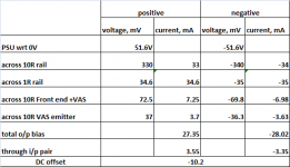
yes Shaan you were correct about 27k res, after discharging the caps (had about 330mV charge on them), They measured correctly. this time i had matched Hfe's of i/p pair and set the pot value to 2.2k before soldering.
So finally success😀
here are the measurements. pl let me know if they are correct. bias seems a bit low. without even adjusting the pot, the offset is 10mV.
So finally success😀
here are the measurements. pl let me know if they are correct. bias seems a bit low. without even adjusting the pot, the offset is 10mV.
Attachments
It has been playing now for the past hour on a test speaker. to be on a safer side I put 10uF 50V NP cap on input and its yet to break-in. I will let it play for atleast 6-8 hours before connecting to my sub.
It would have been straight build if I had taken care of ceramic cap voltage ratings .
Thank you Shaan/thimios/others for your valuable suggestions, help and guidance
regards
Prasi
edit: just for my info, is there a way to increase the o/p bias? would fitting 2 1n4148 in series do it or other operating points of ckt also need optimization?
Last edited:

Adding two diodes will increase total MOSFET bias to around 300-350mA. So idle dissipation will be around 30-35Watt.
edit: on second thought, the bias may be more than 400mA!
Last edited:
Adding two diodes will increase total MOSFET bias to around 300-350mA. So idle dissipation will be around 30-35Watt.
edit: on second thought, the bias may be more than 400mA!
Aha! In different circumstances, that would be a nice test case😀 with lowered supply voltages to manage dissipation.
Yes. If Gate-Source voltage is held constant (as in our case by use of the glass diode) MOSFET bias will depend directly on supply voltage (to some extent).
Last edited:
Can I use 470R trimmers instead of 500R trimmers ?
Hello Patrick.
I guess you are talking about V4. Yes you can use 470R trimmers.
Last edited:
Hello Shaan
If I want to assembly the V4 without the VAS current limiter, so which componets I can left out?
is Q3 also part of the current limiter? can I left it out?
Thanks
If I want to assembly the V4 without the VAS current limiter, so which componets I can left out?
is Q3 also part of the current limiter? can I left it out?
Thanks
Last edited:
Hello Shaan
If I want to assembly the V4 without the VAS current limiter, so which componets I can left out?
is Q3 also part of the current limiter? can I left it out?
Thanks
Q5 and Q6 are the limiters. These are controlled by R15 and R16. If you don't want overcurrent protection during set-up then omit these four components.
You can simulate the same effect as removing these components by setting up the amplifier with both jumpers closed (i.e. shorted). This will electrically remove the two transistors from the circuit without physically removing them.
thanks
Hello,
Another question what is the function of Q4 and Q3?
a close match still required for Q1 and Q2 ? any match is required for Q4 and Q3?
My guess is the for V4 a match is required only between Q1 to Q4? and another match Q2 to Q3?
Thanks
Another question what is the function of Q4 and Q3?
a close match still required for Q1 and Q2 ? any match is required for Q4 and Q3?
My guess is the for V4 a match is required only between Q1 to Q4? and another match Q2 to Q3?
Thanks
Last edited:
Sorry if the question is repeated, but how about the diode and a followed 10R resistor. Is it for protection? Those are in every version of PeeCeeBee. What is their purpose? Thanks
Hello,
Another question what is the function of Q4 and Q3?
a close match still required for Q1 and Q2 ? any match is required for Q4 and Q3?
My guess is the for V4 a match is required only between Q1 to Q4? and another match Q2 to Q3?
Thanks
Q3 and Q4 are the buffers for VAS transistors. Matching not required for normal operation, but is always welcome as it would mean yet better performance. Matching Q1 and Q2 is more welcome than other pairs. The pairs are Q1+Q2, Q3+Q4, Q5+Q6, Q7+Q8, Q9+Q10 and Q11+Q12.
Sorry if the question is repeated, but how about the diode and a followed 10R resistor. Is it for protection? Those are in every version of PeeCeeBee. What is their purpose? Thanks
The diodes provide isolation of the VAS+Input stage power rails from the output stage rails during transients and with 10R they form CDRC filters that attenuate rail ripple in the VAS+Input rails.
Thank you, good i asked. I felt it was not just a dummy protection 🙂 Thanks. Now it is clear.
Q3 and Q4 are the buffers for VAS transistors. Matching not required for normal operation, but is always welcome as it would mean yet better performance. Matching Q1 and Q2 is more welcome than other pairs. The pairs are Q1+Q2, Q3+Q4, Q5+Q6, Q7+Q8, Q9+Q10 and Q11+Q12.
The diodes provide isolation of the VAS+Input stage power rails from the output stage rails during transients and with 10R they form CDRC filters that attenuate rail ripple in the VAS+Input rails.
Thanks.
- Home
- Amplifiers
- Solid State
- PeeCeeBee