Hi Thimios.
Please see Post#2507.
Let's wait for Prasi's tests with two 1R rail resistors. I hope his MJEs are genuine (I have heard of fakes of them getting into market).
Hi Shaan,
I will do it over the weekend, if possible, with GB activity of CRC PSU looming around the corner, I do not know if I will get time.
I will post updates.
So you recommend, 1R rail resistors for initial measurement and everything else as per silk?
Also I have KSC3503/KSA1381 that are from mouser. can also get KSE340/350 from vsrelectronics online shop (do you have any experience with them?). All are ECB.
I will check
1. if BC are still working
2. 1N4148 diode
3. any other? could you add to the list
regards
Prasi
Last edited:
Hi Shaan, one more thing I noticed in your build (page1) is that you didn't mount the mje's on heatsink.
Is it not required?
Is it not required?
So you recommend, 1R rail resistors for initial measurement and everything else as per silk?
Hi Prasi, big rail resistors - when initially testing amp - 10R or even 33R (if bias current is not too big) has no correlation with blowing VAS or other parts for first try.
First try - You can use 33R to see if there are no shorts, wrong connections and etc. Big resistor is a better "safeguard" - when it is something wrong in the circuit.
Do not adjust working current (for example 100mA) with big rails resistors (10R). If you short these resistors after adjustments - the current might change dramatically. Current 1mA or less is OK in this testing stage.
If everything is fine - then - For precise adjustments - use lower value Rail resistors like 1R or better 0R33.
Last edited:
My prototype is on the same way too.Hi Shaan, one more thing I noticed in your build (page1) is that you didn't mount the mje's on heatsink.
Is it not required?
VAS transistors aren't on main heatsink.
http://www.diyaudio.com/forums/solid-state/231662-peeceebee-198.html
Last edited:
Hi Shaan, one more thing I noticed in your build (page1) is that you didn't mount the mje's on heatsink.
Is it not required?
I was using small heatsinks for the each VAS transistor so didn't need to mount them on main heatsink.
VAS and output transistors can be safely mounted in the heatsink as long as heatsink is grounded.


MJEs used, 100uF MOSFET decoupling, 220uF input side decoupling, VAS + O/P mounted on heatsink. RCA input with no volume control. Running from +/-56VDC, being given hell on a daily basis and the cabinet doesn't even provide shielding.
Hi thimios, Shaan,
I have managed to desolder and measure the transistors. MJE's are short / showing as 2 diodes.
I also measured the 22pf comp caps, they are damaged. I had used a 50V part NPO there. Could this be a reason that comp caps failed due to higher voltage of supply resulting in MJE oscillation?
Now I will use KSC3503 (hfe 90) and KSA1381 (hfe 138) with 24pF comp caps (100V).
Is there a need to increase this value? say 39 or 47pF? Its only gonna do subwoofer duty.
i/p transistors are fine, but still going to replace.
I also measured the lats in my tester, and it shows as 2 diodes and same was the case earlier.
probably the tester cant be used to measure laterals.
Last edited:
Hi thimios, Shaan,
I have managed to desolder and measure the transistors. MJE's are short / showing as 2 diodes.
I also measured the 22pf comp caps, they are damaged. I had used a 50V part NPO there. Could this be a reason that comp caps failed due to higher voltage of supply resulting in MJE oscillation?
Now I will use KSC3503 (hfe 90) and KSA1381 (hfe 138) with 24pF comp caps (100V).
Is there a need to increase this value? say 39 or 47pF? Its only gonna do subwoofer duty.
i/p transistors are fine, but still going to replace.
I also measured the lats in my tester, and it shows as 2 diodes and same was the case earlier.
probably the tester cant be used to measure laterals.
Ok I soldered all components and checked for cold joints and shorts and used a 10R 1 W resistor on both rails for initial checking.
As I was about to measure the delV across 10 R res, the 100 R resistor started smoking.
immediately hit the off switch.
I dont know what i am doing wrong, i am open to suggestions.
regards
Prasi
Are your output transistors ok? Any of them blown?
Obviously too much power is going through the resistor. If an o/p transistor is blown this will happen.
Obviously too much power is going through the resistor. If an o/p transistor is blown this will happen.
Last edited:
Are your output transistors ok? Any of them blown?
i do not have any equipment to check them, my transistor tester doesnt recognize them. the same o/p trannies were used in apex fx-8, they were working fine for a long time on different occasions. was using the amp to test some pre's/ buffers, etc
You can unsolder and check with diode tester between each leg and dmm. (check datasheet)
Also check with a dmm for any shorts between the transistors and heatsink.. (you have probably checked the insulation and done that. )
Also check with a dmm for any shorts between the transistors and heatsink.. (you have probably checked the insulation and done that. )
Prasi,have you test using incandescent lamp in the primary side of the transformer together with the protective 10R resistors in the rails?Ok I soldered all components and checked for cold joints and shorts and used a 10R 1 W resistor on both rails for initial checking.
As I was about to measure the delV across 10 R res, the 100 R resistor started smoking.
immediately hit the off switch.
I dont know what i am doing wrong, i am open to suggestions.
regards
Prasi
If you have a new pair of these output fets,fit them,only ONE pair.
Test with a lower voltage using the same protection.
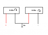
If two regulated power supplies(With the adjustability of the current limiter) are available, use them.
One power supply for eatch rail.Start from 10V(look at the Amperometers).
Last edited:
You can unsolder and check with diode tester between each leg and dmm. (check datasheet)
Also check with a dmm for any shorts between the transistors and heatsink.. (you have probably checked the insulation and done that. )
Hi I have done that, there is no short between h/s and o/p.
Also h/s is earthed by default due to mounting method of heatsink to aluminum base plate.
Hi thimios,Prasi,have you test using incandescent lamp in the primary side of the transformer together with the protective 10R resistors in the rails?
If you have a new pair of these output fets,fit them,only ONE pair.
Test with a lower voltage using the same protection.
If two regulated power supplies(having current limiter) are available use them.
One power supply for eatch rail.Start from 10V(look at the Amperometers).
I always fit MBT before testing any ckt. Plus the 10r for this Amp.
Unfortunately I don't have any more of o/p device. I so probably take a break and look to order more.
No variac for available with me😱
No,i don't mean Variac.Hi thimios,
I always fit MBT before testing any ckt. Plus the 10r for this Amp.
Unfortunately I don't have any more of o/p device. I so probably take a break and look to order more.
No variac for available with me😱
I mean two separate adjustable power supplies.
Do you hear a continuous beep when testing output fets using DMM?
Attachments
Last edited:
No,i don't mean Variac.
I mean two separate adjustable power supplies.
No my dear friend, I don't have those unfortunately. Can you suggest a ckt?
Use two lm317 circuits if two transformers or a transformer with two separate windings available.No my dear friend, I don't have those unfortunately. Can you suggest a ckt?
Last edited:
Hello Prasi.
Is the heatsink connected to PSU ground (not just earthed)?
Did you install higher voltage rated miller capacitors? The recommended minimum voltage is 500V, type being ceramic of any kind. With +/-48V PSU even 100V rated ones can blow up during operation with normal input signal level causing catastrophe, but may not get damaged during test phase and/or low input signal level.
There are two 100R resistors in the feedback section, did they blow up this time or the 10R VAS emitter resistors blew up?
22pF is fine for this amplifier.
To test the MOSFETs you need a piece of wire and a multimeter. For the N MOSFET set your meter in diode test mode and connect the red probe to pin 3 (drain) and black probe to pin 2 (source). Now short pin 1 and 2 with the wire and the meter should show open circuit. Short pin 1 and 3 and the meter should show around a couple hundred or less. If you get both true then the MOSFETs are good. To check the P MOSFET reverse probe polarity and short the same pins as mentioned above with the wire.
Hello Prasi.
Is the heatsink connected to PSU ground (not just earthed)?
Did you install higher voltage rated miller capacitors? The recommended minimum voltage is 500V, type being ceramic of any kind. With +/-48V PSU even 100V rated ones can blow up during operation with normal input signal level causing catastrophe, but may not get damaged during test phase and/or low input signal level.
There are two 100R resistors in the feedback section, did they blow up this time or the 10R VAS emitter resistors blew up?
22pF is fine for this amplifier.
To test the MOSFETs you need a piece of wire and a multimeter. For the N MOSFET set your meter in diode test mode and connect the red probe to pin 3 (drain) and black probe to pin 2 (source). Now short pin 1 and 2 with the wire and the meter should show open circuit. Short pin 1 and 3 and the meter should show around a couple hundred or less. If you get both true then the MOSFETs are good. To check the P MOSFET reverse probe polarity and short the same pins as mentioned above with the wire.
Hi Shaan,
1. The H/S is earthed and PSU 0 V is also connected to earth.
2. I have 1kV 33p caps, I will use those for miller cap.
3. yep, the 100R in feedback got burned this time. 10R VAS resistors are fine.
4. MOSFETS are tested as per your suggestions, they are fine. Rugged beasts those, to have withstood so much abuse.
one more thing is the 27 k resistors are measuring funny, +side slowly measures upto 27k and - side shows 5k.😕
regards
Prasi
one more thing is the 27 k resistors are measuring funny, +side slowly measures upto 27k and - side shows 5k.😕
Are you absolutely sure? This can render all your efforts to make it work to be wasted. The resistors should be equal and 27K.
- Home
- Amplifiers
- Solid State
- PeeCeeBee