VSSA T03
Hi LC
KSA1381 ESTU? /KSC3503 DSTU? what exactly use ? D OR E
I use KSA/KSC having 155-175 hFE and 5,6 pF Miller cap, 2,7 Mhz (-3 dB) with input filter and Zobel in action, now imagine. 😎
@PMI, I cannot make it oscillate even with 1 m antenna at the input, it just shows strong 47 kHz of Tek LCD. 😀
Hi LC
KSA1381 ESTU? /KSC3503 DSTU? what exactly use ? D OR E
Hi, get more exciting here 🙂
Has anyone try how much max voltage for 1 pair J162+K1058 & 8 ohm speaker?
2SA1360/SC3423 like I do 🙂 but you need compensation caps!
Or try slow BD139-140 without compensation caps, maybe it is better 🙄
I want to try VSSA later, with 10uF... sorry Shaan
Has anyone try how much max voltage for 1 pair J162+K1058 & 8 ohm speaker?
Hi Jason try :LC, Shaan:
Any thoughts on some of the alternatives such as 2SA1507/2SC3902 and KSA1220/KSC2690 for the VAS devices? These look to be readily available in same rank Hfe. They seem to have decent specs save for Cob, which is somewhat higher than the coveted A1381/C3503. Other recommended devices?
2SA1360/SC3423 like I do 🙂 but you need compensation caps!
Or try slow BD139-140 without compensation caps, maybe it is better 🙄
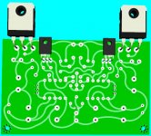
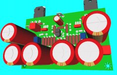
Kang Damanhuri try to draw PCB like this 😀 with big elco'sI try Sir Shaan 🙂
I want to try VSSA later, with 10uF... sorry Shaan
Attachments
Hi Jason try :
2SA1360/SC3423 like I do 🙂 but you need compensation caps!
Or try slow BD139-140 without compensation caps, maybe it is better 🙄
John,
I had a look for those Toshiba types, but alas they are obsolete and no longer available, though by the data sheet they looked wonderful. I have ordered some KSA1220A/KSC2690A and 2SA1507/2SC3902 to try out and see what they are like. Only issue I see is Cob is higher than the best loved devices, but it remains to be heard what these sound like.
I attached the sim files. The models I use are the Cordell models.
There is a lot for a VSSA PeeCeeBee builder to learn from PauloPT sims. If this amp was designed without Lateral Mosfets we would not need KSA/KSC VAS transistors at all. They are used here in order to achieve low distortion by the virtue of their low Cob. These CRT TV drivers have extremely low Cob and as such are beneficial to any Lateral Mosfet amp. And Lateral Mosfets output transistors are used in VSSA simply because it is V Simple SA. Bipolar output transistors would require more than 6 transistors in the circuit, and design goal for this circuit is to use only 6 transistors while at the same time achieving great subjective performance.
The big question is does CCS for input pair improves subjective performance of this circuit and the possible answer may even be NOT.
There is a lot for a VSSA PeeCeeBee builder to learn from PauloPT sims. If this amp was designed without Lateral Mosfets we would not need KSA/KSC VAS transistors at all. They are used here in order to achieve low distortion by the virtue of their low Cob. These CRT TV drivers have extremely low Cob and as such are beneficial to any Lateral Mosfet amp. And Lateral Mosfets output transistors are used in VSSA simply because it is V Simple SA. Bipolar output transistors would require more than 6 transistors in the circuit, and design goal for this circuit is to use only 6 transistors while at the same time achieving great subjective performance.
Right. Bipolar outputs will require at least two more active devices and possibly a pair of 100pF capz at VAS too for acceptable performance and stability, putting more limits on BW and slew rate (sectors where SSAs rule). Laterals are gifts from above. 😀
The big question is does CCS for input pair improves subjective performance of this circuit and the possible answer may even be NOT.
IMO, Subjective=Personal, coz no two minds hear the same way. But if someone says he/she likes the difference then it's all cool. That I don't appreciate the difference doesn't mean I'm a bad listener or the difference is universally bad or the other guy got delusions, it means I have different tastes.
Hi, get more exciting here 🙂
Has anyone try how much max voltage for 1 pair J162+K1058 & 8 ohm speaker?
With one pair of 1058/162 and 8Ohm speakers as much as +/-50V is not a problem even with 150mA bias. Many well known Lateral Mosfet amps from the eighties used one output pair and +/-50V supplies. There are several of them still working in my hometown and Lateral mosfets are famous for their ruggedness and reliability. Even if pushed hard for a long time they will survive. That is one of the good features of Lateral Mosfets, you can utilize much of their nominal power (unlike BJTs). With big heatsinks (like those that PMI use) and +/-50V supplies at least 80W is available with 8Ohm speaker. But I am not sure if some additional changes to the VSSA circuit is required with 50V supplies other than 15K resistor. I would not recommend 50V supplies with 4Ohm loudspeakers although incredible stories exist on local Serbian forums concerning many hours of hard work even with 2Ohm loads!
Thanks very much for that, I have been hoping someone would do that... 😀I attached the sim files. The models I use are the Cordell models.
I noticed the rail caps are on the small side for the sim, was that done for a reason, or are you building your boards with those values?
If you are building w. those, 100u might be too small for rail decoupling on the front end of the amp. (Even though there is not much power being used there, the benefits of the reservoir caps in the supply are reduced b/c of the diode and the 10R.) So, when the main supply rail dips as a result of the output power requirement, not only is the front end supply from that cap only, but current is interrupted b/c the diode stops conducting. The cap after the diode has to supply power to the VAS, and also filter the noise from the diode turn-off...
In any case, good job on the sim!

Shaan,
If you plan to use multiple output pairs good thing to read is
http://documentation.renesas.com/doc/products/transistor/apn/rej05g0001_pmf.pdf
particularly Power Mosfet destruction mechanisms and countermeasures chapter.
Power mosfets are prone to gate parasitic oscilation when parallel output pairs are used!
Hi Pete,
You're welcome 🙂Thanks very much for that, I have been hoping someone would do that...
The 100u are just for the sim. I'll use 1000uF for the build. I have yet to order them, and the feedback caps also. I see only Mouser has Fine Golds but they ask 30€ shipping costs to my country. I'm still undecided about buying them from Mouser or buying instead KA or Panasonics locally. Are the Nichicon's FG worth it?😕If you are building w. those, 100u might be too small for rail decoupling on the front end of the amp.
Last edited:
Not that much, and definitely not for the 1000uF rail caps! I have the FG's, for LC's boards, because I want to build them according to his directions, but I am using the Panasonic FR series on my version of the board....Are the Nichicon's FG worth it?😕
The whole point of this thread is to make an affordable version of VSSA that anyone can build with available parts. And, hopefully others will continue to do just that.
Shaan specifically said no "un-obtainium", no obsolete parts... I have been trying to stay on topic with my build. This is the basic idea that attracted me to this thread in the first place - a good sounding amp that can be built by anyone, anywhere, IF you are willing to put a little time into it.
Having said that, check the main VSSA thread. They must be getting the FG parts somewhere in Europe...

What about the 2200uF feedback caps, any replacement sugestion?Not that much, and definitely not for the 1000uF rail caps!
That's because Shaan is a nice person. 🙂 And I appreciate his efforts and views.Shaan specifically said no "un-obtainium", no obsolete parts...
I did that, seems that only mouser has the 6.3V 2200uF 🙁Having said that, check the main VSSA thread. They must be getting the FG parts somewhere in Europe...
Shaan,
If you plan to use multiple output pairs good thing to read is
http://documentation.renesas.com/doc/products/transistor/apn/rej05g0001_pmf.pdf
Thanks ivan. I'll give it a read.
@Paulo
Thanks for the kind words man. You and a lot of nice and helpful guys here in this thread make it work and keep it going; I appreciate that a lot.
I used FR series for that also. There should be no issues with any good quality low ESR cap, if it fits. The lead spacing of the FR series is the same, the 2200uF cap is one size smaller diameter, and The Panasonic FR series is actually lower ESR than the Nichicon FG series, and it is rated at a longer life.I did that, seems that only mouser has the 6.3V 2200uF 🙁
@Shaan
Don't need to thank me. You're doing a wonderfull job and it's me who needs to thank you for it!
@PMI
Thanks. What about subjective sound quality?
Don't need to thank me. You're doing a wonderfull job and it's me who needs to thank you for it!
@PMI
Thanks. What about subjective sound quality?
Big and ugly can of worms you are opening in this thread my friend, elcos and sound quality... 😀@PMI
Thanks. What about subjective sound quality?
I will give it a shot:
Lower ESR and higher ripple rating, is likely to be best for the 1000uF rail caps, when using a linear filtered supply. This assumes at least a minimal CRC filter in main supply.
The issues with the 2200 uF cap are more complicated, especially given the bias setting using a single resistor (the 15K), and the differences of opinion about paralleling elcos with film caps.
In either case, a clean power supply will have a much greater effect than any choice of local filtering cap.
As you can see from the VSSA thread, other people are trying and using various brands and lines of electrolytic caps. The difference in sound quality will be very small, IF you do a completely fair and controlled test. This would mean comparing similar size and rating caps, but only after 20-50 hours burn-in (and hoping one set did not sit on the shelf somewhere for a year), and only with the SAME power supply with identical noise profile!
In the end, these are filter caps. They are not directly in the signal path, meaning they do not transmit the actual signal that you hear, as opposed to the input coupling capacitor. So, regardless of what people claim, the effect is tiny (assuming similar series resistance and other published specs).
Paralleling caps also has an effect (but it is very subtle). So when you read that someone swapped caps and the sound improved, if you do not know what other caps were in the circuit, it is pretty much meaningless. The "best" elco in parallel with a 10 uF film cap will not be the best elco used alone.
The parallel cap (usually small elco or large film cap), has to be chosen with the bigger elco in mind. LC has chosen the approach of using a very large film cap, to balance a large elco (with likely large-ish inductance at high frequency). Another member (Esperado?) has posted about the "10% solution", which entails paralleling large elcos with smaller ones, chosen in a relationship to the inductance of the bigger cap (this is an elegant solution, but not as simple as it seems, because the values would have to recalculated for each type of elco used, and each application). Shaan, and I think Salas and others, are in favor of avoiding parallel caps completely.
There is a much bigger dependence on the power supply than on the family of filter cap used on the amp boards (assuming low or low-ish series resistance, like any quality low ESR cap). In most cases, elcos have three purposes,
1) local reservoir cap (local to the amp PCB b/c most listening tests are done at low power),
2) filtering noise which made it past the filtercaps in the power supply,
3) isolating circuit stages from each other, especially when used with the type of diode resistor combo we have on this board.
In all cases, the elcos are in the path the supply current takes to the active components (the transistors and mosfets). So any effect on sound quality will depend on the quality of the supply current first.
My plan is to concentrate on the choice of main power supply, and the choice of driver transistors. (None of us really know if the unmatched KSA/KSC pair sounds better than matched lower hfe transistors. We would need both sims AND verification by measurement to determine that.)
I have tried two different linear power supplies, unregulated and regulated, and compared to an old linear Tektronix bench supply which is close to ideal for audio (seen in some of my pics). So far, the bench supply is better, both in measurements and subjective listening tests. As a result (and after some discussion with a couple other people here), I have started working on another linear supply with both VSSA and PeeCeeBee in mind, but, ...
 😀
😀In the end, these are filter caps. They are not directly in the signal path, meaning they do not transmit the actual signal that you hear, as opposed to the input coupling capacitor.
Erm, if I don't get it wrong, the 2200uF caps conduct part of the AC feedback current to/from ground(low AC impedance) and if they aren't linear then the feedback fed to the emitters aren't a true replica/sample of the output voltage, now having extra distortions from the capacitors (which too will be taken as distortion at the output and corrected by the input transistors), only to be amplified by the gain factor and presented phase inverted at the output. Please correct me if I'm wrong which is possible.
The "best" elco in parallel with a 10 uF film cap will not be the best elco used alone.
Exactly.
Shaan, and I think Salas and others, are in favor of avoiding parallel caps completely.
Thus eliminating any chance of belief/doubt to emerge, and also no placebo effect, ensuringing a healthy discussion.
Honestly I am not 100% sure. Have to think about the middle part of that... 😀
Erm, if I don't get it wrong, the 2200uF caps conduct part of the AC feedback current to/from ground(low AC impedance) and if they aren't linear then the feedback fed to the emitters aren't a true replica/sample of the output voltage, now having extra distortions from the capacitors (which too will be taken as distortion at the output and corrected by the input transistors), only to be amplified by the gain factor and presented phase inverted at the output. Please correct me if I'm wrong which is possible.
If so, would a proportion of any remaining noise on the power supply also be amplified?
Either way, I agree that this cap is the more critical to the circuit. I really wish I could measure some of this.
hi shaan
thanks for your pleasant in this thread
i have, a few question may be stupid question for the expert like you, but if you have a time and answer my question or everyone in this thread i'm very very thankyou, cause i'm newbie in amps design, thanks for all.
1. how to set bias into class ab and class a amp?
2. how many pair power mosfet, if i need 100W in class ab and load into 8ohm?
3. what we can use for the power suply rate to drive these amp at full load 100w class ab?
thanks a lot
g.y.w.
If so, would a proportion of any remaining noise on the power supply also be amplified?
These caps will shunt PS noise/hum, but the inherent nonlinearity when conducting AC will add harmonics to the FB voltage which will be inverted and supplied as the inverted correction current to the VAS then to the output. The distortion is generated in the FB node(not in the active stages). So the correction signal tries to correct an error that wasn't there if FB wasn't applied. This is what I think will happen if the caps are too nonlinear, and the reason they are said to need some set-in time, after which the dielectric has a more linear AC character.
I too, am not 100% sure of the above. Need to run some sims when I get back home.
...expert like you...

Please don't insult the real experts. I'm just another curious diy-er.
1. how to set bias into class ab and class a amp?
The default setup is for Class-AB. For Class-A, use a 3.1V zener diode in place of the 4148 diodes, in opposite direction i.e. ndgative leg to the PNP VAS's collecter. Remove the 4148 diodes when you do this.
Please note that there isn't much to get when you bias it to Class-A. In fact performance can get worse.
2. how many pair power mosfet, if i need 100W in class ab and load into 8ohm?
One pair can do it. But you will need higher supply voltage and different input and VAS transistors that can operate at higher voltage.
3. what we can use for the power suply rate to drive these amp at full load 100w class ab?
+/- 40V 250VA/300VA transformer (56V rectified). At least 15000uF/63V capacitance per rail. You'll probably get more than 100W with this supply.
- Home
- Amplifiers
- Solid State
- PeeCeeBee