This is worth a discussion, everyone should have some direction on what devices to use, so they can make informed choices. AFAIK, KSA1381/KSC3503 pair can-NOT be matched in current production D and E devices.Yes these can be used, but, 1)offset will get a mind of its own, and may be 2)more even harmonix than oddz.

I can't speak to the harmonics, but I had no problem adjusting the offset. Offset was stable within a few millivolts from cold (23-25 room temp), to about 55 C. I did not bother matching the KSA/KSC pair because complementary devices were not available. However, I did find that the VAS current can vary quite a bit with temperature and supply voltage. (I posted a Q. about this in the VSSA thread, per your suggestion in earlier posts).
For discussion, here are the components on the pair of boards I have used for testing:
BC550/560, Fairchild/Mouser, matched (note that this was NOT a simple single-point match) thermally coupled (glued)
KSA1381/KSC3503, not matched, with 47pf compensation caps (planning to test w. 22pf, but have not tried yet), w. separate heatsinks.
2SK1058/2SC162, Renesas, Tayda Electronics, with 100R/130R gate resistors to offset differing gate capacitance. (note that if you go by the datasheet, this should probably be 100R/150R, not 130)
Perhaps we should recommend using BD139/140 for those people just starting their build?? Easily available, cheap (even in faster, 16S suffix, Fairchild version only about $0.30/ea), and it should be possible to match these, if needed. Shaan? LC??... with BD139-140 everything is operating correctly. 15-17mA very stable offset...
Then the dancing offset that nikosokey faced was most probably due to oscillation. Modern 'new' and 'improved' devices often bring this with them(not really a 'fault'). Let's wait for more input from nikos.
I don't think you wasted your money, because you can measure a bunch of parts, and reject any outliers. That in itself is worth a few extra C$... (peace of mind and all that) 😀...According to Fairchild the other Hfe ranks are now obsolete, all new KSA will be E rank and KSC will be D rank which will largely preclude these devices where reasonably close matching is needed. Hope I didn't waste my money.
However, with respect, I think you may be trying to do something that is just not possible by concentrating on a single-point hfe match.
Even if you match a pair exactly, they will no longer "match", once installed in the circuit, and definitely not after the offset is adjusted to zero (because they will not be operating at the same point on the curve you measured, anyway).
I think there is more to be gained by matching the input transistor pair, all the resistors that have an effect on the gain in the positive and negative half of the circuit, selecting the gate resistor value to match the N-channel v. the P-channel device capacitance, and so on... my opinion anyway, and I am sticking to it... until the next time I change my mind, 😉
I saw it, you wrote:PMI!
Check this out please!: #588
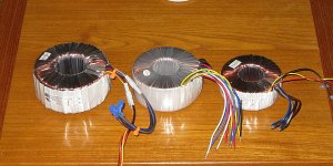
One single 250VA transformer for two channels, with plenty power to spare, but I am not designing a supply for a combination of worst-case conditions, or for class A. note the pic below, the 250VA is the little donut on the right (626VA on the left, and a super-special Hypex 500VA with all the extra goodies in the middle... 😀)250VA for one chanel?
Greets:
Tyimo
I am a bit reluctant to start this discussion here, because it will not satisfy anyone completely, and also I am not in any way opposed to big transformers, or large arrays of filter caps, or the SMPS approach.
The 40~50W, for me, is for peak power, good for a nice extended dynamic range in occasional loud listening, with a single pair of moderately efficient speakers... even then, only for when the neighbors are absent.
50W into 8 ohms translates to 20V and 2.5A rms. At +/-35V DC nominal rail voltage (37V max), my power supply has to be capable of ~90W per channel, peak power. Two channels, plus some losses in the bridge rectifier, and in the transformer itself, and the closest standard size for a toroidal transformer is 250VA.
Note that if you want to design for continuous power, 4 ohm loads, multiple speakers, etc., this post is not for you. In that case the first thing you need is some really LARGE heatsinks first, then some nice big reservoir caps, and only then, a bigger transformer... plus inrush limiting, and output protection, and fuses on the amplifier board, and thermal limit switches...
I have some moderately sized heatsinks rated at 0.65 C/watt, which cost only $12 each, and a small chassis made from a few pieces of industrial-grade aluminum. See post 528, it shows the transformer inside the chassis. At normal listening levels, the transformer only gets barely warm, and the temp rise on the heatsinks is about 12C, meaning, they get warm, but not hot. I have made this kind of inexpensive chassis/supply for other people in the past, and so far none have overheated or failed.
However, when I was doing high frequency continuous sine and square wave tests near clipping, (without the Zobel installed), the temperature rose too much in a matter of a few minutes, and I am aware that some things are left out of my calculations for a true worst-on-worst case analysis.
... which brings me back to the beginning, this will not satisfy everyone 😀
Attachments
Last edited:
ASK
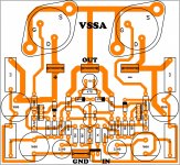
to Mr. LC and Mr. Shaan,
please check, if this is correct?
I have not added to block grounding
to Mr. LC and Mr. Shaan,
please check, if this is correct?
I have not added to block grounding
Attachments
Last edited:
...please check, if this is correct?
Hi.
Arrange the 4007+10R segment so that it meets the large filter capacitor first, and then connects to other areas of the layout.
P.s.: your layout is very cute. Try to make it as soft and currrvy as you can. 😉 😀
Thanks PMI!50W into 8 ohms translates to 20V and 2.5A rms. At +/-35V DC nominal rail voltage (37V max), my power supply has to be capable of ~90W per channel, peak power. Two channels, plus some losses in the bridge rectifier, and in the transformer itself, and the closest standard size for a toroidal transformer is 250VA.
However, with respect, I think you may be trying to do something that is just not possible by concentrating on a single-point hfe match.
Even if you match a pair exactly, they will no longer "match", once installed in the circuit, and definitely not after the offset is adjusted to zero (because they will not be operating at the same point on the curve you measured, anyway).
I wasn't planning on using the the DMM as the definitive match, but rather to place parts that have at least that one point in common together for further matching. I was hoping with 100 pieces of each that I might get a few lower gain PNP and a few higher gain NPN with which to select best compliment devices. I understand the devices need to match where you plan on operating them on their respective curves, but it seems to me easily identifying at least one point in common is a start in the process.
I think it may not be so bad to use these, I was just hoping they would be a little closer. I may just order a small quantity of some other complimentary types to see just how complimentary they really are.
As for the input devices, I believe they are more important to be similar in characteristics. I bought 500 each BC550C and BC560C and should be able to select from those some reasonably matched ones.
Seems like we are both going in the same direction just not the same way... and jumping through some major loops while we are at it. Did anyone bother to ask LC where he got his complementary Fairchild E-suffix parts??? (two pair showed up today along with my boards from the GB)I think it may not be so bad to use these, I was just hoping they would be a little closer. I may just order a small quantity of some other complimentary types to see just how complimentary they really are...
Not that I don't enjoy matching hundreds of transistors... just saying... 😱
I try Sir Shaan 🙂Hi.
Arrange the 4007+10R segment so that it meets the large filter capacitor first, and then connects to other areas of the layout.
P.s.: your layout is very cute. Try to make it as soft and currrvy as you can. 😉 😀
Hi guys!
I see in Shaan's version using BD139/140 there's no compensation cap. Can I assume it isn't needed?
I'm having trouble sourcing in Europe 2200uF 6.3V Fine Gold caps. I can get 1000uF that fits the pcb - I'm using PMI's pcb. With 1000uF I calculated a -3dB point 1.59 Hz. Can I use these? 😕
Thanks.
I see in Shaan's version using BD139/140 there's no compensation cap. Can I assume it isn't needed?
I'm having trouble sourcing in Europe 2200uF 6.3V Fine Gold caps. I can get 1000uF that fits the pcb - I'm using PMI's pcb. With 1000uF I calculated a -3dB point 1.59 Hz. Can I use these? 😕
Thanks.
Last edited:
I would not assume that, without testing. However, it is likely that the 47pF I am using can be reduced to 22 pf, perhaps less. It is also probably less important with a slower VAS transistor pair.I see in Shaan's version using BD139/140 there's no compensation cap. Can I assume it isn't needed?
I would guess you can, but Shaan or LC may correct me on that. Lower value cap == less filtering==more potential noise. But, the difference may be very small.I'm having trouble sourcing in Europe 2200uF 6.3V Fine Gold caps. I can get 1000uF that fits the pcb - I'm using PMI's pcb. With 1000uF I calculated a -3dB point 1.59 Hz. Can I use these? 😕
Thanks.
I would caution against cutting too many corners though. Good sound is usually a result of many contributing factors. Sooner or later, there is one compromise too many.
Hi guys!
I see in Shaan's version using BD139/140 there's no compensation cap. Can I assume it isn't needed?
I would add to what PMI said, that you better test it before using it.
I use 2K2 as feedback resistor which decreases the bandwidth of the whole amp from that with 1K (the BW is independent of gain by virtue of CFB), plus slow VAS trannies (fast enough for the purpose). The combination of these two choices electrically renders the amp usable with nominal gain upto around 200kHz or so, which is pretty good to me. So far I have not encountered any stability related problem in my peeceebee without capacitor compensation. I think the inherent bandwidth limiting is at work here. However, the music appears to be free of any limitation. 🙂
With 1000uF I calculated a -3dB point 1.59 Hz. Can I use these?
Yes. 🙂 Try them, if hum appears, revert to 2200.
Sooner or later, there is one compromise too many.
Exactly. Life......
@ Shaan:
I believe I finally have some time to do that test at low bias that you suggested, and a couple more things other people have been interested in.
The pair of boards I am using for testing has been running without the 470R, 2 diodes only. I assume I can just use any old pot or trimmer in place of the resistor for adjustment, I would rather not have to remove the diodes.
Any other test conditions? Unregulated supply, bench supply? test freq 1KHz or something else?
Also - which version/suffix of BF139/140 are you using w/o compensation caps? In other words, the slowest, or the fastest (BD139/BD140-16S)?
Any other test conditions? Unregulated supply, bench supply? test freq 1KHz or something else?
Regulated, 10KHz, if possible. 🙂
Also - which version/suffix of BF139/140 are you using w/o compensation caps? In other words, the slowest, or the fastest (BD139/BD140-16S)?
The zlow ones... No suffix.
Thanks in advance Pete.
Thank you Pete and Shaan for your answers. 🙂
Thanks again.
I don't have a scope so I can't test it before use it. What would be the recommended value for BD139/140 compensation caps?I would add to what PMI said, that you better test it before using it.
Thanks again.
- Home
- Amplifiers
- Solid State
- PeeCeeBee