2SK209: Matched versus Unmatched
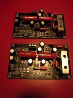
Just completed a premium BA2018 build where the transistors were matched and 0.1% resistors were chosen. The resulting PCB sounds significantly different than the stock version with a more refined sound ideal that my ears hear as “smooth control.”
Think that this approach might benefit the Pearl 3 as well, so prepared two trace curves for 1) eight 2SK209s taken straight from the cut strip and 2) a set of 8 2SK209s matched at Idss=4.75mA.
Cf. these two graphs below.
The closer traces of the matched set suggest that audio performance accuracy will improve after matching. Has anyone here already tried matching -- either the 2SK209s or the alternate 2SK107s?
Am thinking a premium build with 2SK209 matching and 0.1% resistors might be worthwhile.. To this end, it would be helpful if the P3 PCB was available separately. Any possibility of this, 6L6?
Attachments

Hello Craigl59,
hello all other PEARL3 - builders,
I did something very similar what CraigL59 describes in his post #4222. I can confirm his findings.
I also matched my 2SK209. I tested around 100...
I matched all parts from left to right channel.
I made two different pcbs on my own. I prefer my version for single OPAmps.
I tested different linear power supplies. In my first iteration it was a single psu for both channels. Later I changed to dual mono
supplies.
I tested different OPAmps - they also influence the sound slightly...
There are so many ways which lead to Rome - or to audiophile heaven...
Greets
Dirk
p.s.. Sorry, but I don't want to search all my posts in this thread, where I described all that above
@cubicincher:
Yes, this is important:
"I matched all parts from left to right channel."
Did this as well with the BA2018 build in order to ensure that the matching would affect both channels equally and the soundstage would benefit.
Also am using dual mono PSUs everywhere and this makes a big improvement.
How did you make the duplicate PCB?
Dirk, I admire your diy fanaticism! Dual PS for the Pearl 3? Crazy! I like it!
Which OPAmps do you prefer?
Which OPAmps do you prefer?
Hello Craigl59,
how do you mean your question about 'duplicate pcb'?
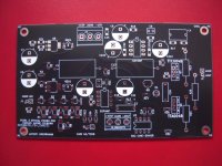
I had the schematic from Wayne Colburn out of this forum and used KiCad6. I made the pcbs only for use by myself.
Does that answer your question?
Cheers
Dirk
how do you mean your question about 'duplicate pcb'?
I had the schematic from Wayne Colburn out of this forum and used KiCad6. I made the pcbs only for use by myself.
Does that answer your question?
Cheers
Dirk
Attachments
Hello WBS,
there are a few very good OPAmps for me.
Dual OPAmps: TI1656, LME49720, LM833 (in this sequence, and many more (some of the JRC - OPAmps are also great)
Single OPAmps tested: OPA 827 and LT1115
But the differences are small / marginal between some of the OPAmps. I am sure, that it would be difficult to judge in a blind test?
Cheers
Dirk 😉
Yep and thanks.Hello Craigl59,
Does that answer your question?
Cheers
A bit late to the party, but I posted a pair of LTspice decks earlier in this thread - one for the front end, and a separate one for the RIAA EQ / output stage.Has anyone posted an LTSpice sim of the Pearl 3? If it's OK to do so, I cobbled one together to play around with values and would be happy to post. I don't know protocol on such things so please enlighten me if that's not appropriate to post.
Thanks!
Feel free to ask me any questions. I might even post updated versions, since I’ve improved on the originals a little since posting them.
Would be interesting to compare notes / see how well results agree. I was mostly focused on adaptations for 2SK170 in place of 209’s, and in dialing in EQ optimizations.
Another thing I was looking at was cascode BJT rolling & checking stability with alternates. I don’t think too many builders have experimented with that yet. The stock ZTX851 cascode is hard to beat.
I also built a folded cascode version in spice, but haven’t built it IRL. While it’s easy to assemble using the kit PCB, the benefits look marginal… a few extra volts on the JFET drains, which can help with the higher current K170 FETs, but that’s about all.
If anyone’s interested, I can post that spice deck, though it strays from the original topology and is more of a curiosity than anything I’d recommend except on a ‘caveat emptor’ basis.
LTspice decks here: https://www.diyaudio.com/community/threads/pearl-3-burning-amp-2023.404054/post-7618414
The version I posted is set up to mimic 2SK209 JFETs. You can ignore the two diodes and the tiny value cap surrounding the cascode transistor - those were added to facilitate folded cascode simulations, but do not alter the results with the original circuit configuration.
The version I posted is set up to mimic 2SK209 JFETs. You can ignore the two diodes and the tiny value cap surrounding the cascode transistor - those were added to facilitate folded cascode simulations, but do not alter the results with the original circuit configuration.
Another one sings. Tested a bunch of opamps and got stuck with simple LF353.
Beautiful sounding phono pre! Thank you Wayne! (and of course Mark for the UDP3).

Beautiful sounding phono pre! Thank you Wayne! (and of course Mark for the UDP3).
As some asked via PM.
Supra Lorad has 3 wires plus an extra shield cable. I wired brown to +, blue to - and green to GND. The extra shirld cable is not connected to P3 but connected to common chassis ground where PE from IEC inlet is connected. Super silent that way.
Supra Lorad has 3 wires plus an extra shield cable. I wired brown to +, blue to - and green to GND. The extra shirld cable is not connected to P3 but connected to common chassis ground where PE from IEC inlet is connected. Super silent that way.
Well, this is embarrassing. I actually populated the boards shortly after receiving them a year ago, before the build guide was posted.
Last week I finally finished the @rhthatcher power supply and assembled the Modushop chassis in anticipation of bringing it to BAF 2024. Unfortunately, I have a problem with the right channel voltages.
The power supply puts out +24.67V and -24.8V, so far, so good. When I hook up both boards things get wonky. After correcting their polarity, both blue LEDs light up but the red LED on the right channel does not. When checking input voltages, the right channel shows +9.42 and -9.87 volts. The left channel is +9.3, -9.86 volts. After disconnecting the right channel, I get +22.23, -22.63 volts to the left channel. What the???
@mhenschel I'll check when I have time after BAF.
@Craigl59 Thanks for the tip. I'll take a closer look. I vaguely remember reading somewhere in the thread that they are sensitive to static electricity. Although I was careful to ground myself when working with them perhaps they were damaged.
@Craigl59 Thanks for the tip. I'll take a closer look. I vaguely remember reading somewhere in the thread that they are sensitive to static electricity. Although I was careful to ground myself when working with them perhaps they were damaged.
Think it more likely they are reversed; had to order new ones for my fix as they are hard to desolder. Check the numbers.
- Home
- Amplifiers
- Pass Labs
- Pearl 3 Burning Amp 2023