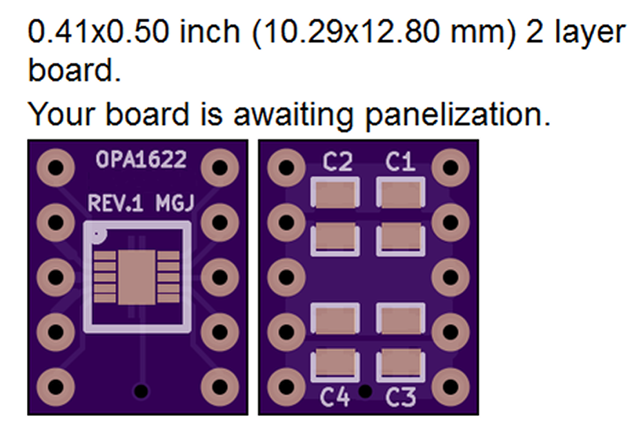
I'd suggest laying out your own SMD-to-DIP adapter PCB, and including well-chosen SMD capacitors right on the adapter PCB, for local power supply bypass. Here's an example that I did back in 2015-16 for the unusual OPA1622 which comes in a 10 pin package.

^ See ... now I feel foolish. I could have just found that and asked... "Would something like this work here?".
Thanks as always, Mark!
Thanks as always, Mark!
I share the concern with adding contact points with stacking DIP-8 packages.
I make a lot of SOIC-8 to DIP-8 adapters, and to eliminate the extra contact points between the adapter board and the socket (which is then plugged into a socket on the board), I make sure to flow solder from the pins through the board into the contacts of the socket. If this is then soldered into the main board, there are no friction points, but if plugged into another DIP-8 socket, the high-quality round pins make good contact with the round-pin sockets soldered into the main board.
...
I've also used thumbscrews on a several phono preamp builds. These are actually captive, with press-collars and springs - they stay in the lid/panel.
View attachment 1358487
Did you get the entire captive screw as a kit, or in parts?
Yes. The scary screw driver. It's just four screws in the special chassis. But, if it is stuffed in a rack or other difficult area, there would be that.That would be dependent on any difficulties a user has (or not) with operating a screwdriver…
The phono board chassis is just an open box. Board right there, part in question is exposed and easy to get to. Pluck it out, install another.
I was driving the prototype P3 with the lid unscrewed so I could lift it... and yes, it's on a seven inch shelf, so I don't necessarily want to reach to the back with the screwdriver every time. It's unnecessary wear and tear. That's the whole point of thumbscrews.
IMHO, the whole point of using an op amp is, well.. to roll the op amp... and that means opening the box often enough.
Yes, I did think "outside the box" and figured I could keep it open but then it'll accumulate some dust and when we get the Big One it might get damaged.
And then there's the domestic tranquility thing... in my home office I pretty much do as I fit, but my audio salon is in reality "The Living Room"... so I already got like three racks, two pairs of speakers, woofers, plus three feet wide for records -in rotation (*)- and we don't have a coffee table... the last thing I want to have in there is bare electronic boards.
I think I'll go with thumbscrews.... now the next question... will red ones sound better than orange ones? Do they make Pass Blue thumbscrews?
(*) That is a pun... records, rotation, get it?
Last edited:
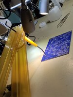
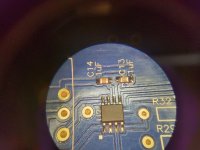
First time soldering SMD components myself. I tough I will use the microscope at work.
It was a big help - as expected - but the component holder made the real difference today.
Glad I work with smart colleagues 🔬 😅
It was a big help - as expected - but the component holder made the real difference today.
Glad I work with smart colleagues 🔬 😅
Attachments
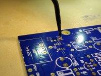
I have continuity across GND and IN on one of my boards and I cannot figure out what the culprit is. I'll attach pictures, but I can't get my phone camera to get a good picture of the back of the pcb without bluring.
I'll post pictures and get back after it tomorrow.
Any ideas?
I'll post pictures and get back after it tomorrow.
Any ideas?
Attachments
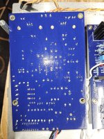
Buy some acetone and some q-tips, and have a scrubbing session out on yr back patio. If it doesn't reveal a solder bridge or cold joint, at least yr boards will look proper.
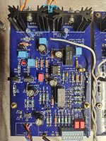
R15 and R18 are shorted on 5712.jpg. Just in general, you need to clean the boards with alchohol, use a toothbrush to scrape away all of the excess, then go over the close terminals with a sharp pointer to make sure they are all separate. One of the close 3-prong regulaters on 5223.jpg also look shorted. But do both boards carefully and then let us know.
Cleaned the board as best I could, R15 and R18 are in series as far as I can tell, though I tried to separate those joints.R15 and R18 are shorted on 5712.jpg. Just in general, you need to clean the boards with alchohol, use a toothbrush to scrape away all of the excess, then go over the close terminals with a sharp pointer to make sure they are all separate. One of the close 3-prong regulaters on 5223.jpg also look shorted. But do both boards carefully and then let us know.
I had the continuity broken, I tested it several times across the GND and IN pads, as well as from the GND and IN pads across the pads of Q1 thru Q4 and thought I was good, the continuity was broken, then I flipped the board over and soldered the input wiring back and continuity came back.
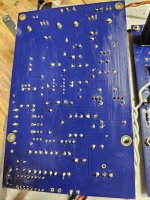
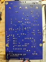
I pulled the input wiring back out and I'm still stuck with continuity. Here is another picture. The regulator pins are not solder shorted.
Attachments
Last edited:
Sounds like something is loose based on your description. Check all of the solder joints for firmness. I went with terminal blocks to avoid repeated soldering of the ins and outs. Have also found it helpful to desolder troubling areas and carefully redo them. The Hakko desoldering tool is very good here but is expensive. Good luck. The next step would be a part issue and this would require a lot of testing. Did you check the SMD continuity carefully when putting them in? Check them for shorts. Easy to do because of their adjoining through holes for substitute jfets.
Cleaned the board as best I could
in general, you have way too much solder on most of soldering points
doesn't need to be a problem per se, but increasing possibility of any of them being "cold", while also being troublesome if having two pads close
Check the soldering of R8 on the jfet-side. On the first set of pictures it seems it might be a loose connection.
in general, you have way too much solder on most of soldering points
doesn't need to be a problem per se, but increasing possibility of any of them being "cold", while also being troublesome if having two pads close
I appreciate the observation, I will make a note for myself moving forward.
Sounds like something is loose based on your description. Check all of the solder joints for firmness. I went with terminal blocks to avoid repeated soldering of the ins and outs. Have also found it helpful to desolder troubling areas and carefully redo them. The Hakko desoldering tool is very good here but is expensive. Good luck. The next step would be a part issue and this would require a lot of testing. Did you check the SMD continuity carefully when putting them in? Check them for shorts. Easy to do because of their adjoining through holes for substitute jfets.
Las night my last act was gently touching and poking around on the board while testing, and was unable to identify a potential culprit.
Again this morning though I had a situation where the board seemed to resolve itself. With the board still in position, suddenly there was no continuity between the GND and IN pads, and no continuity between IN and any other grounding points. The tests across the GND pad and Q1-Q4 gave expected results and tests across the IN pad and Q1-Q4 gave expected results.
I left the board alone for a couple quick minutes to check on work emails, returned to my workbench and confirmed again there was still no continuity. Without moving the board I soldered in the input wiring again, but when I finished.... continuity had returned.
Could this possibly be an issue with one of the capacitors given this?
When I had initially completed the amp and hooked it up to my system the other channel work and performed great but this channel had hiss and a significant lower gain, to the point I didn't think the channel was working at all. But when I disconnected the working channel and turned the volume up, I could heat music on this channel but like I mentioned the gain was much less with lots of his and that is when I suspected an issue with GND.
Last edited:
^ For fun... maybe try this. Take any capacitor you have around that is not in a circuit => just a spare part laying around.
Measure the DC voltage across the cap and see if it's under 1V or so. If not, safely and properly discharge the cap until it measures under 1VDC.
If you have two DMMs (maybe even different models / manufacturers) -
Hook DMM#1 to the cap with the probes set "properly" (+) to (+) and (-) to (-) and set it to measure DCmV.
Set DMM#2 to measure resistance. Place the probes of DMM#2 on the cap with the polarity of the probes the same as DMM#1. Watch the values on DMM#1 and DMM#2 simultaneously. Swap the probe polarity of DMM#2 ... Go back and forth a few times for fun. See what happens when the voltage reaches "0V"... See how high the voltage / resistance climbs.
@markf31: Again, sounds like a loose/intermittent soldering problem. Setup your DMM to read (=beep) the continuity from GND and + then use a plastic pointing tool to press down on each leg of the SMDs individually. Should the DMM stop ringing you've found a problem.
You are doing something physical with the board when you solder the in wires and analyse what this is -- some movement is cause the change to continuity and once you identify this you can start to identify the problem -- likely a poor soldering joint.
You are doing something physical with the board when you solder the in wires and analyse what this is -- some movement is cause the change to continuity and once you identify this you can start to identify the problem -- likely a poor soldering joint.
- Home
- Amplifiers
- Pass Labs
- Pearl 3 Burning Amp 2023