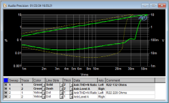
Excellent question.Is it @1kHz? And how much gain was P3 set to?
The MM (Rfb=220R||2.2k) is specified at 49dB and mine is running hot at 50+ owing to the high gfs of the selected 2SK170's I chose. You only need 40dB for moving magnet carts.
Yes it is at 1kHz.
Tomorrow will adjust Rf for 40dB gain, and run the test at both1kHz and 20kHz.
Last edited:

There seems to be two "religions" regarding TT grounding (if you want chassis/earth galvanic connection with signal gnd or not):
https://philipsag9015.home.blog/2020/01/18/humm-of-turntable/
Some does not want Earth/chassis direct connected with signal gnd.
From the above link it can also depend if one of the signal gnd from cartridge has connection with cartridge shell / tonearm. If this is the case then it is easy to make a ground loop. He writes that care should be taken if trying to measure this using a DMM (magnetizing cartridge with DC-currents from DMM).
I look forward to get some learning experience with this.
My first implementation will be what my head says is correct. Then we will see if I change my mind......
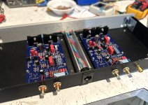
Why on "earth" (get it?) would you use NTC to get an unstable ground connection???I spent a bit of time doing the internal PSU wiring in P3 chassis.
Regarding grounding scheme I will try to explain my plans.
In UDP3 there are no connection between PSU Gnd and chassis.
UDP3 chassis in connected to Earth via the Y/G wire.
Earth is shield in umbilical and is going to P3 chassis as you can see in first picture (Y/G wire).
The turntable chassis terminal at back panel will go to P3 chassis screw (not wired yet).
Then I intend to wire the signal gnd on each P3 PCB to the P3 chassis screw but via 2 x NTC to have a ground lift.
Then these connections will be the only signal gnd reference to chassis / Earth.
I don't like the idea to connect the P3 signal gnd directly to the P3 chassis screw.
If I do I will have two points where signal gnd is connected (at the PSU input terminal block and chassis screw).
In all my other builds I have a ground lift using a NTC and I have no hum in any of these builds.
The only thing which could talk for connecting the signal gnd to chassis screw directly is if a turntable really "like" to have direct signal ground via its chassis screw (I have not yet any experience with this).
NTC stands for "Negative Temperature "Coeficient" = rising resistance when cold and falling res. when warm.
If you (have no idea why, nothing scientific to prove, it´s useful) insist on isolating "ground" from "ground", at least use a standard
resistor........ 10 ohms or like. NTC´s are not the right place for this.
@MEPER wrote: "Some does not want Earth/chassis direct connected with signal gnd."
That´s why you use "output ground" for chassis connection and NOT "input ground"
@MEPER wrote: "My first implementation will be what my head says is correct."
Of course. Why take good, proven electronic engineering for a fact?? Exiting..... isn´t it ? 🤣 🤣
Last edited:
The use of NTC is a "safety reason". If current is raising then impedance goes to almost zero.
Also the e.g. IronPre has this "feature" on PCB. It has been normal practice to use NTC as ground lift "resistor" in this forum. I have learned it from here 🙂
I see the riaa as "just" a preamp and I just try to implement what has worked perfect for other builds. My system so far is very silent 🙂
So I think I use good proven electronic engineering 🙂
E.g. post #2793 / 2794 in this thread:
https://www.diyaudio.com/community/...er-your-interest.390509/page-140#post-7518349
Any reason not to do something similar in P3?
I always want to learn new stuff. With P3 spilt in two chassis should not make any difference regarding this. At least not in my build with safety ground in one wire in umbilical. So seen "logical" same as one chassis. The yellow/green wire connects the two chassis together.
Christmas in January! My Pearl 3 kit has arrived! Now the fun begins.
Actually NO.The use of NTC is a "safety reason". If current is raising then impedance goes to almost zero.
Also the e.g. IronPre has this "feature" on PCB. It has been normal practice to use NTC as ground lift "resistor" in this forum. I have learned it from here 🙂
I see the riaa as "just" a preamp and I just try to implement what has worked perfect for other builds. My system so far is very silent 🙂
So I think I use good proven electronic engineering 🙂
You´re confusing integrated amp stuff, that have built-in Power transformer and their safety measures.
Pearl3 does not have that. And since you isolate the power supply from the riaa cabinet, there´s no reasons not to
just connect the ground/TT-ground directly to the chassis terminal.
There seems to be two "religions" regarding TT grounding
No, there is not “two religions.” There is only one, and that is minimum/zero hum in your system.
Hum has a way of not following the rules, so try a few different configurations if you have issues and use the one that is quieter. What works in your system may not work in mine. My configuration, which is quiet, might not work in yours. You have to try different things if you have hum issues… Once it’s quiet, wonderful, you are done! Enjoy the music.
That’s it. Simple!
Actually NO.
You´re confusing integrated amp stuff, that have built-in Power transformer and their safety measures.
Pearl3 does not have that. And since you isolate the power suplly from the riaa cabinet, there´s no reasons not to
just connect the ground directly to the chassis terminal.
Pearl 3 has a transformer. Which means mains is in the chassis. There is no different safety measures with this or an integrated.
The provided PSU board has a ground lift, (so it does “have that”) using a diode bridge, but a power NTC would work as well. The point being that IF mains faults, it must flow to earth, which the diodes will happily do, and the NTC would as well, as it’s going to instantly heat and become low resistance.
Anyway, the suggested configuration does have RIAA ground connected to chassis through the ground post, which is firmly attached to bare metal chassis. (It’s also important to insure that all chassis panels have electrical conductivity to each other for maximum shielding.)
I don't have ground lift in UDP3 PSU chassis (PSU gnd not connected to chassis). I do that in P3 chassis and transfer the Y/G wire in umbilical.
As long as there are wires going from a chassis with mains to a chassis without mains you can in theory transfer mains voltage to the chassis without mains.
I will start with having the usual signal ground to chassis ground lift to check that out first. All chassis in my system have earth connection to chassis and it could be "noisy". All my DIY amps have ground lift (an exception may be the Korg as from memory it has signal gnd connected via PCB stand offs. to chassis).
If I experience noise with P3 riaa it is easy to bypass the ground lift to try that out. I will report back when time comes......
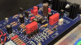
I've been holding off soldering jfets to the P3 PCB's.
The decision as to what Jfets to use has been resolved by deciding to use PCB sockets (see below) for the op-amps.
With some help found some 2sk209's already soldered to tiny adaptor boards.
As one option considering using two 2SK170's in parallel vs 4 2sk170's.
I think that I may even try rolling in and out some PF5102's and 2N5470's.
The jfets solder to another gender plug and are swappable.
I suspect there will be much more difference from jfet rolling rather than op-amp rolling.
Preci-dip
https://www.mouser.com/ProductDetail/437-8018700310001101
Last edited:
Attachments
@DualTriode
would those headers be suitable for resistor leads or is the hole too big?
Those header sockets are too large for typical resistor leads.
Try the pin header below, the resistor leads solder to the short part of the pin and the long end of the pin plugs into the socket. Works well. grip things with needle nose plyers.
Carefully break off one pin for each resistor lead.
https://www.mouser.com/ProductDetail/Preci-dip/800-10-010-10-001101?qs=sGAEpiMZZMvlX3nhDDO4ACZluy6VyHAGesTKtQVJJ2M=
Thanks DT
Last edited:
@Mark Johnson ,
Thanks
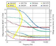
Welcome information, noise is good to know.
BF862 looks like it needs an audition.
Distortion signatures and gain may also vary when swapping jfets.
Thanks DT
Another Pearl 3 birthed. I salvaged a chassis, K170’s, etc from my Pearl 2 build. The small boards are nice, so I want to go with a smaller, steel chassis in the future and optimize my wiring scheme a bit. Using a simple CRC outboard supply for now, also from Pearl 2 (though I downsized the toroid). Anyways, it’s done and sounds great - thanks Wayne and co for your efforts!
Attachments
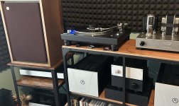

Thanks fellas. I'm definitely preferring it to my old Pearl 2, which was no slouch. For those still building, I had to adjust R27 to set my opamp bias properly, so it could be wise to solder in some pin sockets there, then once you find the right value, solder them in. Or better yet, do all that testing/measuring before bolting everything together (I'm bad at this step)
- Home
- Amplifiers
- Pass Labs
- Pearl 3 Burning Amp 2023