Ok.
So the question remains... mounting orientation for larger-bodied resistors?
my concern was proximity to the capacitors. I had this problem with the original Pearl but the caps were further away.
I was planning to value these to, in part, set the output voltage. Maybe I'd be better off adding a pre-regulator for this?
They will make negligible heat. Mount them any way you can fit them. No worries.
Wait - When you say "I was planning to value these to, in part, set the output voltage. Maybe I'd be better off adding a pre-regulator for this?"
What were you planning to do? Are you going to put in larger resistors to drop voltage? If you do that you need to calculate voltage drop at the resistor and power dissipation. It will generate heat if you crank up that resistor.
I suggest sticking to the formula on those filter resistors and let the regulators do their job. The regs have heatsinks. It's a proven formula. It works, and the P3 sounds GREAT this way. Try this as a default, then experiment.
Last edited:

@mhenschel
…maybe build it as designed first? Make sure everything works, see how it sounds, and only then go futzing with it?
The Pearl 3 boards can take quite a range of input voltage from the PSU, +/-35 to +/-16.1 (which are the 7815/7915’s input maximum, and regulated output + min dropout, FWIW) but in practice you really want 2+ volts more than target output on the input, so just think +/-17V is minimum for input. Is more better? Not particularly, but won’t hurt.
Randy in a previous post did some dissipation calcs, things don't get hot, the currents are too low. I use 10R 2W resistors in my PSU, it’s what I had on hand when I put it together, works fantastic.
@6L6
I purchased the Pearl kit complete with parts and I do intend to build it as deigned and supplied... happily.
The kit came with a PSU board which I'm not intending to use for the Pearl but thought I might use for something else. But I did read the specs for it and am trying to follow those... like you're suggesting I do. They say use 1W resistors but the ones I can source easily won't fit... so I asked. When the answer turns out to be, well they don't need to be 1W they could be 1/4W or whatever I wonder why the spec at all if they don't mean what they say? Am I supposed to question everything... but build what I'm told? There's a disconnect there.
Maybe my background works against me here. My dad was an electrical engineer in the building industry. He wrote specs for particular good reasons and expected that they would be followed by the contractor -- as a matter of safety and honesty. Lives depended on it and the owner should get what he paid for. The specs and drawings weren't a puzzle to solve -- they were written to follow to obtain the desired outcome. Attention to detail mattered.
Maybe I'm looking at this wrong.
@6L6
I purchased the Pearl kit complete with parts and I do intend to build it as deigned and supplied... happily.
The kit came with a PSU board which I'm not intending to use for the Pearl but thought I might use for something else. But I did read the specs for it and am trying to follow those... like you're suggesting I do. They say use 1W resistors but the ones I can source easily won't fit... so I asked. When the answer turns out to be, well they don't need to be 1W they could be 1/4W or whatever I wonder why the spec at all if they don't mean what they say? Am I supposed to question everything... but build what I'm told? There's a disconnect there.
Maybe my background works against me here. My dad was an electrical engineer in the building industry. He wrote specs for particular good reasons and expected that they would be followed by the contractor -- as a matter of safety and honesty. Lives depended on it and the owner should get what he paid for. The specs and drawings weren't a puzzle to solve -- they were written to follow to obtain the desired outcome. Attention to detail mattered.
Maybe I'm looking at this wrong.
Much the same for me.
I am a retired ME.
Much of my work was dealing with material substitutions.
The Contractor would complain that the "thing" would not function as specified.
Most often the problem was that the Contractor had substituted materials.
You bought it and you changed it, you own it. It is a zero sum game.
Here we help each other.
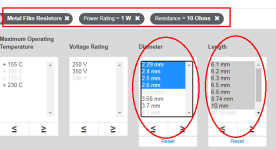
I find it really helpful to use the parametric search facility at mouser.com when hunting for resistors.
The Pearl 3 build doc says that the 1W resistors on the PSU board, are fitted into a PCB footprint whose lead spacing is 12.7mm (0.500"). So I told mouser's search engine to find me some resistors whose bodies are noticeably shorter than 12.7mm. At the same time, I also asked for the smallest diameters available, since a small diameter 1W resistor will fit more easily onto ANY pcb, than a large diameter 1W resistor. For 10 ohm, 1 Watt resistors, with suitably short bodies and suitably small diameters, mouser had these in stock today: (link)
Very, very handy!!
Attachments

Last edited:
@DualTriode
LOL -- that resonates!!!
site inspections were fun. my dad also had a prominent clause in the spec that said stuff that was installed wrong and/or not to spec would be ripped out and replaced with materials and methods that were compliant.
this clause was often enforced at site meetings with the owner in attendance. often the contractor complained "where does it say that?" my dad had the unerring ability to open the spec -- some of which were pretty thick -- at precisely the correct page, turn the volume towards the contractor and ask him to read aloud. no wiggle room there.
dad tried to invoke this clause as early as possible on something minor... to not cost too much and to make the point that he meant it.
The wires used for connecting the two P3 boards power (V+, Gnd, V-):
Do you put a bit of solder at the stripped ends (assuming that litze wire is used) or do you put "raw" stripped wire ends in the screw terminals?
For maintenance I like to put a bit of solder on the litze. Then if presure is not very high you can take the wire out without the ends are damaged so you can use same wire again. If just "raw" wire the litze tends to break of easy if you need to release the wires for board maintenance. Screw pressure on bare copper will probably give the best electrical connection (with high presure a cold welding will take place but then you can do it only once).
My choice will probably be to put a little bit of solder on so lizte is "glued together". The solder can crepe a bit with high presure so screw have to be adjusted a bit after some time. I know there exist these terminal pins you can solder or crimp on but I will not use them for this project.
I also like the Mouser search function.I find it really helpful to use the parametric search facility at mouser.com when hunting for resistors.
The Pearl 3 build doc says that the 1W resistors on the PSU board, are fitted into a PCB footprint whose lead spacing is 12.7mm (0.500"). So I told mouser's search engine to find me some resistors whose bodies are noticeably shorter than 12.7mm. At the same time, I also asked for the smallest diameters available, since a small diameter 1W resistor will fit more easily onto ANY pcb, than a large diameter 1W resistor. For 10 ohm, 1 Watt resistors, with suitably short bodies and suitably small diameters, mouser had these in stock today: (link)
Very, very handy!!
I start with the brand an series that I prefer.
I select the largest size that will fit the space.
Bigger runs cooler.
The smaller commercial resistors have higher wattage ratings only because the ratings are more relaxed than say the mil-spec resistors.
Thanks DT
The wires used for connecting the two P3 boards power (V+, Gnd, V-):
Do you put a bit of solder at the stripped ends (assuming that litze wire is used) or do you put "raw" stripped wire ends in the screw terminals?
For maintenance I like to put a bit of solder on the litze. Then if presure is not very high you can take the wire out without the ends are damaged so you can use same wire again. If just "raw" wire the litze tends to break of easy if you need to release the wires for board maintenance. Screw pressure on bare copper will probably give the best electrical connection (with high presure a cold welding will take place but then you can do it only once).
My choice will probably be to put a little bit of solder on so lizte is "glued together". The solder can crepe a bit with high presure so screw have to be adjusted a bit after some time. I know there exist these terminal pins you can solder or crimp on but I will not use them for this project.
I think stranded. The microphone cable is likely not Litze.
Yes solder is good.
@MEPER Tin the wire ends so they dont fray.
@mhenschel What is your exact question, and has it not been answered already? I’ve absolutely lost the train of thought. Also, not sure how @Mark Johnson is “missing the point”, again, please clearly state what it is you are looking for information about/on.
Thanks. 🙂
@mhenschel What is your exact question, and has it not been answered already? I’ve absolutely lost the train of thought. Also, not sure how @Mark Johnson is “missing the point”, again, please clearly state what it is you are looking for information about/on.
Thanks. 🙂
I hate to keep talking about ground, but looks like the Pass Labs XP-17 phono preamp ties the phono ground to the output grounds. Should we be doing this on the pearls? The following is also a quote from Wayne's pearl 2 manual: "The turntable ground should attach to the signal ground, not the chassis ground (unless you find that it is quieter that way)."
Attachments
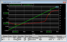
Is it @1kHz? And how much gain was P3 set to?In MM, Overload Margin - at 24.3mV cartridge output, P3's THD+N% reaches 1% (compared to less than 0.004% at 5mV). Thus 13.7dB relative to 5mV
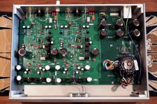
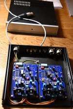
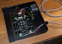
I spent a bit of time doing the internal PSU wiring in P3 chassis.
Regarding grounding scheme I will try to explain my plans.
In UDP3 there are no connection between PSU Gnd and chassis.
UDP3 chassis in connected to Earth via the Y/G wire.
Earth is shield in umbilical and is going to P3 chassis as you can see in first picture (Y/G wire).
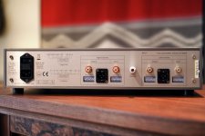
The turntable chassis terminal at back panel will go to P3 chassis screw (not wired yet).
Then I intend to wire the signal gnd on each P3 PCB to the P3 chassis screw but via 2 x NTC to have a ground lift.
Then these connections will be the only signal gnd reference to chassis / Earth.
I don't like the idea to connect the P3 signal gnd directly to the P3 chassis screw.
If I do I will have two points where signal gnd is connected (at the PSU input terminal block and chassis screw).
In all my other builds I have a ground lift using a NTC and I have no hum in any of these builds.
The only thing which could talk for connecting the signal gnd to chassis screw directly is if a turntable really "like" to have direct signal ground via its chassis screw (I have not yet any experience with this).
Regarding grounding scheme I will try to explain my plans.
In UDP3 there are no connection between PSU Gnd and chassis.
UDP3 chassis in connected to Earth via the Y/G wire.
Earth is shield in umbilical and is going to P3 chassis as you can see in first picture (Y/G wire).
The turntable chassis terminal at back panel will go to P3 chassis screw (not wired yet).
Then I intend to wire the signal gnd on each P3 PCB to the P3 chassis screw but via 2 x NTC to have a ground lift.
Then these connections will be the only signal gnd reference to chassis / Earth.
I don't like the idea to connect the P3 signal gnd directly to the P3 chassis screw.
If I do I will have two points where signal gnd is connected (at the PSU input terminal block and chassis screw).
In all my other builds I have a ground lift using a NTC and I have no hum in any of these builds.
The only thing which could talk for connecting the signal gnd to chassis screw directly is if a turntable really "like" to have direct signal ground via its chassis screw (I have not yet any experience with this).
Attachments
I hate to keep talking about ground, but looks like the Pass Labs XP-17 phono preamp ties the phono ground to the output grounds. Should we be doing this on the pearls? The following is also a quote from Wayne's pearl 2 manual: "The turntable ground should attach to the signal ground, not the chassis ground (unless you find that it is quieter that way)."
Please review the build document. It is attached similarly in Pearl as XP-17. The RIAA boards have a center ground point, which is attached to the ground post with the white wires in this example.
Of course, you should see if it’s quieter one way instead of the other in your system. YMMV, so try it and see.
In all my builds (three, so far…) the PCB ground wire attached to the ground post, which is thence firmly attached to chassis is the quietest. All RCA connections are isolated from chassis.
- Home
- Amplifiers
- Pass Labs
- Pearl 3 Burning Amp 2023