Are there any plans to offer just the PCBs in the store? I have all the parts already in my drawer.Kits will return in about 2 weeks
Not at the moment.Are there any plans to offer just the PCBs in the store?
For a snubber to be effective it needs a resistor in series with the capacitor to dissipate the energy of the ringing. Hagerman shows how: https://www.hagtech.com/pdf/snubber.pdf
By and large, snubbers are not necessary in low power regulated linear supplies -- it's a solution in search of a problem.
By and large, snubbers are not necessary in low power regulated linear supplies -- it's a solution in search of a problem.
By and large, snubbers are not necessary in low power regulated linear supplies
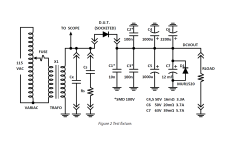
The article in Linear Audio magazine (R.I.P.) showed a lot of measured data with, and without, snubbers at 100mA of DC current -- relatively "low power" in audio equipment.
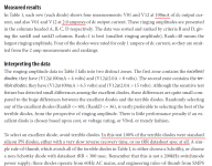
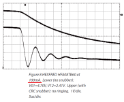
Four dozen different diodes were tested with the same transformer in the same fixture, and every single one of them stimulated the transformer secondary into oscillatory ringing. Adding a snubber completely eliminated ringing, every single time. I've attached one of the Figures from the article; with no snubber {lower trace} a HEXFRED diode provoked ringing, and the ringing completely disappeared {upper trace} when a snubber was added. This particular diode was ranked "excellent" at both 0.1A and 2.0A of DC current; yet it provoked oscillatory ringing. They all did; every last one of them.
Sadly, Linear Audio magazine has closed down and ceased publication. About the only way to get their articles (that I'm aware of) is to buy the complete library of ALL Linear Audio articles. Sold for USD 99 in the diyAudio Store, and perhaps other places I don't know about.
Attachments

At the end of the article you cite (LinearAudio Vol 5) the author (Morgan Jones) states: "We have been chasing a demon which doesn't exist, then made worse by having the wrong parts in the wrong place."
I religiously use snubbers in power amps. I see no necessity of using a snubber in the power supply for the Pearl3...and in any event the snubber needs a resistor to dissipate the energy in the form of heat.
Meanwhile, to detect a problem, assuming you don't have a spectrum analyzer or VNA, sweep the broadcast band with an AM receiver and see if you can hear the oscillation.
The article I cite appears in Linear Audio volume 10 (pages 97-110) and the author is not Morgan Jones. Way back in volume 5, Jones's article dithers around with equivalent circuit models but makes very few actual time domain measurements on transformer+diode+cap+load, and shows no scope traces. The vol.10 article is full of measurements made on actual hardware -- crucially: with, and without, snubbers.
The advice to "sweep the broadcast band with an AM receiver" came originally from Rick Miller; and unfortunately it is misguided and not correct. Sadly, the AM broadcast band extends only from 565 kHz to 1605 kHz, but an actual real-world transformer secondary plus snubber resonant frequency is a factor of 5 lower, at 100 kHz, as can be seen in the attachment to post 5,604. 2 horizontal divisions per period, at 5 usec per division, equals 10 usec per period. Frequency = 1/1E-5 = 1E+5 = 100 kHz. Nothing for an AM radio to receive. I am surprised it didn't occur to you to make a quick check whether the wiggles were, or were not, within the AM band.
One nice feature of the LA volume 10 test fixture is: it's very easy to trigger an oscilloscope at just the right instant to capture the oscillatory ringing. Indirect measurements using radios or spectrum analyzers are unnecessary; you can capture the bell-ringing event itself, and the subsequent ring a ding ding, in the time domain. And display it on the scope, as exemplified in post 5,604.
Attachments

This is all very amusing -- we can take the two P3 boards with different power supplies, feed the results into a Dif Amp and see if we can measure or hear a difference.
The pernicious effect of "ringing" is (borrowing from an Analog Devices application note) bipolar junctions which conduct when they aren't supposed to conduct.
The pernicious effect of "ringing" is (borrowing from an Analog Devices application note) bipolar junctions which conduct when they aren't supposed to conduct.
Hi Guys,
I am gathering parts for the Pearl 3. I have the same question MEPER had in an early post (and I don't see an answer): the umbilical cord between PSU and preamp boards is specified as three conductors + shield. Examples are Mogami W2549 and Carnae L-4E6S. The Mogami wire comes up as a two conductor plus shield. The Canare comes up as 4 conductor plus shield. Exactly what should I be sourcing here?
Thanks,
John
^ There are a number of options. Personally, I like the thickness / girth / substance of the L-4E6S, so that's what I (think I) used. The smaller 'microphone' cabling I had around didn't feel right to me for a power umbilical. No technical reason for my choice.
I used the shield as intended. I used one conductor each for + and - supplies, and I tied the other two conductors together for a 'lower resistance' GND. Not a lovely photo, but it may help. I'm not in any way implying I made the best choice, just illustrating one example that seems to have worked out OK.

I used the shield as intended. I used one conductor each for + and - supplies, and I tied the other two conductors together for a 'lower resistance' GND. Not a lovely photo, but it may help. I'm not in any way implying I made the best choice, just illustrating one example that seems to have worked out OK.
@jminassi - I'm not sure. I'm not terribly picky. I've got a box with various cables, and I'm desperately trying to dwindle it down and not buy more wire / cable. I likely reached in and grabbed what looked like it would work.
IMO, any typical / flexible cable works. I did balanced outs, so I used 1 + shield and 2+ shield. It was most likely something like at Mogami 2552 (or maybe something thinner) and 2330. None of my build pics reveal the marks, and I don't have the P3 at hand.
@chede - Thank you. I have to give credit where it's due. I am reasonably certain I got my bootlace ferrule tool at the recommendation of @Mark Johnson circa 2019. It's an invaluable part of my 'wiring kit'.
Ok Patrick, thanks for the information.
I have a question about the switch for the power supply. A SPST switch is denoted under comments. But the part number is for an E-Switch SPDT. Is this an error? Does somebody have the correct part number?
Thanks,
John
I have a question about the switch for the power supply. A SPST switch is denoted under comments. But the part number is for an E-Switch SPDT. Is this an error? Does somebody have the correct part number?
Thanks,
John
Ok Jim. I think I see what's going on. The SPST version of that E-Switch is not stocked and is twice the price. I'll order the SPDT version.
Thanks,
John
Thanks,
John
Amazon multi-pack will do the trick for switches. And if you cook one when soldering (they can be delicate) - you'll have extras. Here's an example. I bet you find more if you search for MTS-101

The kits are available again. Ordered a couple and now I hope for suggestions based on all your collective and individual experiences and findings on how to build the 'ultimate' Pearl.
They are delicate indeed. if you apply too much heat the contact can just melt off the switch housing.Amazon multi-pack will do the trick for switches. And if you cook one when soldering (they can be delicate) - you'll have extras. Here's an example. I bet you find more if you search for MTS-101
- Home
- Amplifiers
- Pass Labs
- Pearl 3 Burning Amp 2023