
homemodder said:
One question though, when you did the last simulations between the 2 did you change both the LTP current source and vas current source or only the vas.
Hi,
I changed both. That was the comparison from the start.
PB2 said:
John, I read you at the start saying that you just want to understand the differences so I am aware that you have no plan to change. I'm just trying to add to the understanding, and throw in my main reason for the CCS preference which is to eliminate the electrolytic cap. I do also wonder why we're not seeing the expected rise in distortion at LF. Might want to try 1 Hz or .1 Hz.
No problem Pete.
I appreciate the points that everyone has made. I see that technically the CCS is the better way, and that the biggest problem with the bootstrap is the electrolytic cap. What I have been trying to do is weigh the harmful effect, and determine if it justifies changing the design. The fact that the cap has a life span and will eventually fail needed to be considered too. The one I have for this is a 100V Nichicon rated for 5000 hours at 105*C.
I think I can expect many hours of trouble free use.
Besides, the way I get sick of things, this may only be around for a year or so. 🙂
In the end, I feel comfortable with the choice, and wouldn't have any reservations about doing it this way in the future.
I had a malfunction with my power supply. It seems that the rectifier diodes (1N5406) were not up to the task of charging all of those filter caps. Two of the four failed, and went short circuit. This happened as I plugged the transformer in, and tripped the panel breaker.
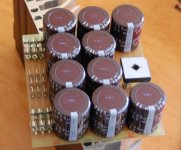
SO, I designed and build a new one, with the GBPC25 rectifier. I made the shape different, square rather than rectangular. I think two of these will fit better in the chassis.
Doing things in a rush, i made the fuses a little too close to each other. I have slipped a thin piece of plastic between each.
Attachments
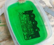
Not lime Jello, boys and girls...
I put some final touches on my new board layout, ready for etching.
My new supply of blank boards is still not here, but I did have a few pieces of double sided left. I used one that was big enough and went ahead and etched the board. I have a pretty good system going for this and I only use enough acid / peroxide mix to do one board. I then discard that mix. I have tried to re-use it in the past, but it has lost all of it's potency. Better a fresh batch every time.
For trace repair if needed, I use a paint marker. I gave up trying to find that magic Sharpie that this mix will not eat. Paint marker works beautifully, dries fast and is absolutely impervious to the acid mix.
Attachments
Fun board pic.
I have taken to putting the component values on the board "silkscreen" - it saves a lot of time and prevents mistakes.
My first try doing it, I made the font too small and it wound up being next to useless. Here I have values that are easily read.
This is the finished board. Hopefully I didn't frack something up.
Trust in my relatively good luck when it comes to this.
andy_c said:Well John, nobody can accuse you of wasting time! 🙂
Hi Andy,
No, I'm full speed ahead when I'm ready and properly motivated. I'll get this one done and if all goes well, I'll get bored with it again and start another project. 😀
No, I'm in this one to the bitter (or sweet) end. Six of these, 2 homemade serious heatsinks, another one of those dinky power supplies, chassis, etc, etc...
I'm assembling the board now. It is the best I've done so far - everything fits as it should. Pics to come.
Assembled, but not tested. I thought Id get a couple pics before I smash it with a sledgehammer when it doesn't work. 🙂

The bottom:

The bottom:
Your boards look amazing for a home brew! What method of transfer do you use to get the image onto the board? Is the silkscreen done by laser toner transfer?
Bravo, MJL, good to see such progress.
What zoble/inductor will you use? (don't see one on board)
Very good reading this thread, bootstrap Vs. CCS,
can now understand how both play out electrically
and harmonic wise.
hope it works..OS
🙂
PS..Don't smash it mail it to me .We are all broke/poor
in US😀 😀
What zoble/inductor will you use? (don't see one on board)
Very good reading this thread, bootstrap Vs. CCS,
can now understand how both play out electrically
and harmonic wise.
hope it works..OS
🙂
PS..Don't smash it
mail it to me .We are all broke/poorin US😀 😀
ostripper said:
PS..Don't smash it
in US😀 😀
So are we here in the UK 🙁
jaycee said:Your boards look amazing for a home brew! What method of transfer do you use to get the image onto the board? Is the silkscreen done by laser toner transfer?
Hi jaycee,
Thank you very much.
I use a laser printer for the traces and the silkscreen. The paper I use is the Staples basic photo paper (as recommended by Tom Gootee). After I do the silkscreen, I spray the top of the board with clear lacquer - this makes th black printing more vivid.
ostripper said:Bravo, MJL, good to see such progress.
What zoble/inductor will you use? (don't see one on board)
Very good reading this thread, bootstrap Vs. CCS,
can now understand how both play out electrically
and harmonic wise.
hope it works..OS
Thanks ostripper,
I will mount the Zobel at the binding posts. I used to put this on the board, along with the inductor, but changed it for this to make the layout less complicated. Besides, I believe these are better off-board.
The inductor is just ~10 turns of varnished wire around a ~4ohm resistor.
Well, thanks to the Wall Street boyos, we all might be a little poorer in the coming months. 700 billion...😱
ostripper said:
hope it works..OS
Well, it didn't. Not at first anyway.
Here's a valuable lesson: when you are mocking up a new layout with different devices (the new 2SA970/C2240, MPSA18), you will want to make sure that you limit the reasons why the amp doesn't work by using brand new devices. Recycling used parts from previous prototypes is probably ok if you know for certain they work properly. When you have had a situation where you drove a prototype amp too hard with less than ideal (read completely inadequate) heatsinking, then you need to be careful.
I melted a couple of outputs in said prototype and stripped the board of usable parts. Unfortunately, the drivers were kept and I re-used them in this one. I forget that when outputs go, they usually take the drivers along for the ride.
So, after trying a few different things, I removed the drivers and checked them. Both were compromised.
With new drivers installed, I try again and bingo! It's all good.
Limited testing so far as I don't have it attached to the heatsink yet, but it looks really good. Very clean high frequency square wave, VERY stable, without a Zobel.
glad you got it 2nd time around..Well, it didn't. Not at first anyway.
I always just populate my boards with LPT ,CCS ,Drivers..,
temp tack a couple of 47 ohm emitter resistors on drivers
(High power headphone amp
 )
)play with bias ,do measurements, feel up all the trannies😀
sometimes just leave it on all night.
Then and only then will I solder the OP section in.
I learned this with repairs , only
 smoked up 1-2 amps
out of hundreds.
Just can't afford to do it any way else🙂
BTW , your amp is very close to the blameless I will make
in november except I'm using active CCS ("patch" of quasi,
self,your amp, and any other idea that is sound.)
I built the quasi but felt he didn't go far enough with its
development. You have done a lot more simulation/testing
in your thread than many which is good.
Once you start really running the amp in a "real world"
environment you see where sims fall short..(offboard zoble
board layout, etc)
hope to hear a report on how it sounds..
😉 OS
ostripper said:
You have done a lot more simulation/testing
in your thread than many which is good.
Once you start really running the amp in a "real world"
environment you see where sims fall short..(offboard zoble
board layout, etc)
hope to hear a report on how it sounds..
😉 OS
It sounds pretty darn good, OS. 🙂
I'm listening right now. "Redemption Song" - Bob Marley.
I have enough heatsink now 😀

I did some testing. 20kHz square wave.

100kHz square wave.

The above were done with no Zobel. Also, running perfectly stable while listening without it. This is the first amp that I've built that will run stable without the Zobel.
I will do some capacitive load tests tomorrow, to see just how stable this amp is.
Like that heatsink(too many holes to drill for me) .. I use big
P4 or socket A heatsinks bolted to L brackets.
Glad to see it playing music.
The zoble is most critical with NO load , thats when I saw
oscillation on my quasi nmos.
On my sub amp I use a zoble just for the "hell
of it" because the subs crossover inductor kills any
reactance anyway.
Still, a modern amp with "fast" OP devices can easily
pick up RF from all our modern high tech "toys"
better safe than sorry..OS
BTW- neat heatsinked "load" in the backround!!
ostripper said:The zoble is most critical with NO load , thats when I saw
oscillation on my quasi nmos.
Still, a modern amp with "fast" OP devices can easily
pick up RF from all our modern high tech "toys"
better safe than sorry..OS
BTW- neat heatsinked "load" in the backround!!
Load or no load: stable. It's sitting now wide open to the world not 3 feet from this computer (temporarily without a case), a plasma monitor, wireless phone and cradle, plus all of the other krap I have around here and still no sign of oscillation.
I'll be using a Zobel and Thiele network anyway, I just thought it was worth mentioning as I have never been able to get away without it before.
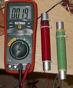
That's my 8ohm 100 watt dummy load. It's a P3 cooler sawn in half with 10 power resistors between. It can get pretty hot.
My 1000 watt, 2 ohm dummy load:
Attachments
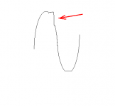
I have a clipping "problem" at 20kHz. The sine wave top breaks harshly on the down slope. I don't have a pic of this, but I drew a bit of an illustration below.
Am I right in assuming this is caused by the EF on the VAS going into saturation? If so what is a cure?
Playing with the simulation, if I increase R7 (collector to ground on the EF) from 4.7k to 10k the problem is reduced. What I'd like to know is if this will work in the actual amp and will it have a detrimental effect on the performance.
This shows a little at lower frequency, but is very minor and not as harsh as at 20kHz.
Attachments
Me thinks you have to much Ic variation in your VAS,
maybe ground collector of Q7 reduce r5 to 2K.
could be the drawback of no active current source-
less Linearity.
maybe ground collector of Q7 reduce r5 to 2K.
could be the drawback of no active current source-
less Linearity.
It is often described as sticking.
Does search help?
What happens if you reduce R5 (emitter degeneration + CCS) to 1 or 2k?
Will a Baker clamp around the VAS help?
Does search help?
What happens if you reduce R5 (emitter degeneration + CCS) to 1 or 2k?
Will a Baker clamp around the VAS help?
Reducing R5 sounds like a good idea, I'd like some more standing current in the VAS driver. Right now there is only about 100µA to turn off Q8. I'd probably decrease the resistor to 1k or even below. 680 ohms will give just below 1mA standing current.
Something else that can be tried is collector of Q7 to collector of Q8 instead of resistor to ground, this will make sure only the faster Q7 can saturate. Baker clamp is another possibility. A diode which can take full rail-to-rail voltage across C5 with anode towards Q8 collector. Maybe not as good though as this will add some nonlinear capacitance in parallell with cdom.
Decreasing or removing R7 is not a good idea, it will make Q8 saturate even harder and possibly blowing Q7 on clipping if it is removed altogether.
Lowering R2 and R3 even more might also help if it's not saturation of the VAS that is the problem.
- Status
- Not open for further replies.
- Home
- Amplifiers
- Solid State
- Patchwork Reloaded: Circuit Optimization and Board Layout.