Hi John,
maybe this is where perception comes to play, it may not be as subjective as some of us may believe but small differences in designs may influence how we perceive the outcome.
By reading your comments, you have more or less made up your mind regarding the sound coming from the amp that you designed. It is what you have been searching for.
I am getting the feeling that you are confirming that the simulations are matching your ears. Believe me John, if you enjoy what you hear and it is how you perceive it should sound like, there is no simulation or measurement in the world that can prove your ears wrong.
I would say that you have reached your musical Nirvana, few of us have ever achieved this and most of us probably never will. You have done a great job.
andy_c said:
The strange thing is, he saw an increase in simulated distortion going from 200 Hz to 20 Hz even with the constant current load on the VAS. This makes no sense to me, as the loop gain of the CCL version should be the same or higher at 20 Hz than at 200 Hz. I'm baffled by this.
Oh, LOL, I'm just casually commenting here rather bored with the subject myself. I probably should drop out because I don't care enough to read every post.
Let's remember that the cap in the FB loop provides more FB at LF which complicates things. I would short R1, R34, R25 and C11 to remove all other LF factors from the equation, then do the distortion comparision again. I'd guess that something is going on with those long time constants in the PSU rails and/or feedback cap.
I seriously doubt if there is an audible difference between the two, except in clipping, and I'd take the CCS just to eliminate the electrolytic cap.
Pete B.
andy_c said:Regarding SPICE models of electrolytic capacitors, Cornell-Dubilier has an app note about that in this PDF file. Here's what they say:
"Typical series inductance values of radial and screw-terminal capacitors are about 1-2 nH/mm terminal spacing. This value does not vary significantly with temperature or frequency, so this portion of the impedance modeling is simple."
Thanks Andy,
I'm trying to wrap my head around it and I'm working on an element ladder that can approach what there are saying. My rudimentary model was demonstrating an impedance increase - 10X higher at 20Hz than at 1000Hz, so I did do something right.
I'll play around some more.
Nico Ras said:I would say that you have reached your musical Nirvana, few of us have ever achieved this and most of us probably never will. You have done a great job.
Hi Nico,
I don't know about Nirvana, but I'm being honest when I say that it sounds great. This is coming from one who doesn't think there is much difference between one amp and the next, as long as they are designed and implemented correctly.
This is also coming from one who is flying by the seat of his pants, one who has the minimum of understanding. There are guys here who have forgotten more than I'll ever know.
True is true though and I can't say it sounds mediocre when it does not. I can't say there is something not quite right when that just isn't the case.
I'm a ways away from the finished product though. I just got the new cascode and mirror transistors today - 2SA970/2240. I need PC board which is not here yet. I need to complete the board layout. Tests on the final layout and component selection.
MJL21193 said:Thanks Andy,
I'm trying to wrap my head around it and I'm working on an element ladder that can approach what there are saying. My rudimentary model was demonstrating an impedance increase - 10X higher at 20Hz than at 1000Hz, so I did do something right.
I'll play around some more.
I think a series RLC model should be fine. The app note gets pretty fancy because they're looking for models suitable for switching regulators. The ripple performance of switching regulators is very sensitive to capacitor characteristics.
Their 1-2 nH per mm of spacing, together with about 0.2 Ohms series R should do the trick.
PB2 said:
Oh, LOL, I'm just casually commenting here rather bored with the subject myself. I probably should drop out because I don't care enough to read every post.
Hi Pete,
I can tell that you are becoming frustrated with my obstinance again.
I didn't want this to degenerate into an argument over what topology should be used. A discussion on the merits of each is what I intended. As far as this design goes, yes my mind is made up. I will not change the current configuration.
PB2 said:
I seriously doubt if there is an audible difference between the two, except in clipping,
This is my point exactly.
andy_c said:
I think a series RLC model should be fine. The app note gets pretty fancy because they're looking for models suitable for switching regulators. The ripple performance of switching regulators is very sensitive to capacitor characteristics.
Their 1-2 nH per mm of spacing, together with about 0.2 Ohms series R should do the trick.
Hi Andy,
I'm baffled. I have re-run the simulations at 20Hz, giving it more time to resolve, but the results are the same. Distortion for the CCS is still nearly as high as the bootstrapped at this frequency.
Is there another mechanism at work here that will increase distortion at low frequency with the CCS version?
Yes, I changed the inductor to 10nH and left the R alone.
MJL21193 said:Is there another mechanism at work here that will increase distortion at low frequency with the CCS version?
Not that I can think of. My only thought would be to run the transient analysis with a really big stop time, like 100 sec or even longer - as long as you can - to see if the low-frequency transient of the capacitors charging up is fully settled out.
andy_c said:
Not that I can think of. My only thought would be to run the transient analysis with a really big stop time, like 100 sec or even longer - as long as you can - to see if the low-frequency transient of the capacitors charging up is fully settled out.
Well, it's not happening. Longer runs equal even lower distortion for the bootstrapped. After 100 seconds, it's less than the CCS.
The figure?

Attachments
Okay, but we weren't talking about bootstrapped vs. CCS/CCL just a minute ago. The issue was why the 20 Hz distortion of the CCS/CCL version was more than the 200 Hz distortion of the CCS/CCL version. Absent a SPICE quirk with simulation time or similar, I can't see why this should be.
As an aside, it might actually be that the bootstrapping capacitor is so large that the increasing distortion as frequency decreases is not seen until a frequency considerably lower than 20 Hz. That would be a good thing.
So, in short, it would be interesting to see:
1) 20 Hz vs 200 Hz distortion of bootstrapped version (using long simulation times).
2) 20 Hz vs 200 Hz distortion of CCS/CCL version (using long simulation times).
I'm not trying to convince you of anything, and it makes no difference to me whether CCS/CCL is better or worse than bootstrapped. It's just that previous simulations resulted in an apparent contradiction that would be good to resolve.
andy_c said:
1) 20 Hz vs 200 Hz distortion of bootstrapped version (using long simulation times).
2) 20 Hz vs 200 Hz distortion of CCS/CCL version (using long simulation times).
I'm not trying to convince you of anything, and it makes no difference to me whether CCS/CCL is better or worse than bootstrapped. It's just that previous simulations resulted in an apparent contradiction that would be good to resolve.
I'll do this Andy and post the results.
First, I want try a run at a lower frequency to see if this backs what you say about the feedback cap.
Be back in a flash...
The harmonic spectrum results shouldnt surprise too much, I was expecting this, but what is surprising me is that THD should be lower than the case with bootstrap. The lower distortion at low frequencies with ccs usually compensate for the higher HF ones.
One question though, when you did the last simulations between the 2 did you change both the LTP current source and vas current source or only the vas.
The lower high frequency odd order distortion is one of the reasons many love bootstrap circuit, and compare it to valve sound. Hugh from aksa likes this circuit and I have never come accross anyone that had something bad to say about his amps sound.
Current sources degrade at higher frequecies, but this is baffling me, is the bootstrap circuit superior at high and low frequencies.
This must have something to do to do with the dynamic impedance.......
MJL21193 said:
I'll do this Andy and post the results.
First, I want try a run at a lower frequency to see if this backs what you say about the feedback cap.
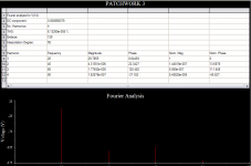
Fundimental = 5Hz
stop time - 2000 seconds (a looooong run)
It's showing - a bit. This is 10 times greater than at 20Hz.
Attachments
andy_c said:
So, in short, it would be interesting to see:
1) 20 Hz vs 200 Hz distortion of bootstrapped version (using long simulation times).
2) 20 Hz vs 200 Hz distortion of CCS/CCL version (using long simulation times).
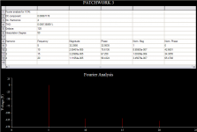
Here they are:


These ran for a long time. 500 seconds at 20Hz, 50 at 200Hz.
Lower distortion on both counts for the CCS as opposed to the bootstrap. Surprised that distortion at 20Hz was better than 200Hz for the bootstrap.
I will see if I have time later to run these again, for verification.
andy_c said:Ahhhhh, it all makes sense now 🙂.
Yes, looking better. I used my cap model in the bootstrap version.
I forgot that the low frequency stuff needs an incredibly long time to get accurate results. Each of these took more than 10 minutes.
Still, look at those figures. It's not as cut and dried as it was made out to be, with low frequency edge going to the CCS, and the high going to the bootstrap.
MJL21193 said:
Hi Pete,
I can tell that you are becoming frustrated with my obstinance again.
I didn't want this to degenerate into an argument over what topology should be used. A discussion on the merits of each is what I intended. As far as this design goes, yes my mind is made up. I will not change the current configuration.
This is my point exactly.
John, I read you at the start saying that you just want to understand the differences so I am aware that you have no plan to change. I'm just trying to add to the understanding, and throw in my main reason for the CCS preference which is to eliminate the electrolytic cap. I do also wonder why we're not seeing the expected rise in distortion at LF. Might want to try 1 Hz or .1 Hz.
andy_c said:
I think a series RLC model should be fine. The app note gets pretty fancy because they're looking for models suitable for switching regulators. The ripple performance of switching regulators is very sensitive to capacitor characteristics.
Their 1-2 nH per mm of spacing, together with about 0.2 Ohms series R should do the trick.
Andy, they mention screw terminals for those caps and this suggests that they're computer or PSU grade that are of different construction with multiple attachment points to the plates. Most common electrolytics have one attachment point. I would not normally worry much about non-linear capacitor effects, but with the very low numbers here it might be a consideration. My point was that we're not even sure that the SPICE model is valid at these very low distortion levels. The RLC model for the cap is still obviously a linear model.
Pete B.
Some interesting cap references:
http://www.intusoft.com/nlhtm/nl65.htm
http://www.intusoft.com/nlhtm/nl76.htm#A_Nonlinear_Capacitor_Model_For_SPICE
http://www.intusoft.com/nlhtm/nl44.htm#modeling
http://www.kemet.com/kemet/web/homepage/kfbk3.nsf/vaFeedbackFAQ/53D5333B4453253585256BCD004EBC04/$file/TechTopics%20Vol4No5%20Sep94.PDF
http://www.kemet.com/kemet/web/homepage/kfbk3.nsf/vaFeedbackFAQ/0C37C2134D52DDBE85256BCD004EBC0C/$file/TechTopics%20Vol8No2%20Jul98.PDF
Not saying that they all apply to this situation.
PB2 said:I would not normally worry much about non-linear capacitor effects, but with the very low numbers here it might be a consideration. My point was that we're not even sure that the SPICE model is valid at these very low distortion levels. The RLC model for the cap is still obviously a linear model.
Yeah, at these sub-ppm distortion levels at low frequency, the cap distortion could very well dominate. I don't know how to model capacitor distortion in SPICE. I bought the Cyril Bateman CD, so I'm familiar with the nice work he did. I know he found that non-polar electrolytics have lower distortion than their polar counterparts. Might be something to consider. Mouser has the Nichicon non-polars for good prices.
Edit: Here's Cyril Bateman's web site:
http://uk.geocities.com/cyrilb2@btinternet.com/
Tonight, while waiting for these sims to run, I plucked some transistors from a dead Kenwood receiver that I got at Goodwill for $2.00. I got about 20 each of 2SA992 and 2SC1845 - about $27 worth right there from B&D. Nice devices too.
A bunch of lesser beings: 2SA733 and 2SC945. About 20 each of those.
4 each of the ubiquitous outputs 2SC3854 and 2SA1490. These go with the other 2 pairs that I found in another receiver.
A good haul, for 2 bucks.
Long leads, I just had to cut them out.
A bunch of lesser beings: 2SA733 and 2SC945. About 20 each of those.
4 each of the ubiquitous outputs 2SC3854 and 2SA1490. These go with the other 2 pairs that I found in another receiver.
A good haul, for 2 bucks.
Long leads, I just had to cut them out.
- Status
- Not open for further replies.
- Home
- Amplifiers
- Solid State
- Patchwork Reloaded: Circuit Optimization and Board Layout.