MJL21193 said:
Hi Pete,
Thoughts on the appropriate values for an equivalent RLC circuit for this? My interest in this is high enough to dig deeper.
Ok, I used an RLC of 100uF, .2ohm and 250nH. At 20Hz it's not showing a difference in the low frequency distortion figure - still .001%
I doubled the L and R, no change. I doubled again - no change.
It was only when I had the L up to 8uH and the R up to 6.4ohm that I saw a 0.0000004% difference.
Something wrong here? Or is this a case of too much importance being attributed to an very minor and insignificant scenario?
Nico Ras said:Hi John,
I have been reading our fellow members opinions with interest and I also have been a bootstrap fan for many years, but what they are saying makes absolute sense.
Hi Nico,
I like to have a good reason or two to make changes that will increase complexity. So far there have been a few reasons, but none that stand up to scrutiny in the simulation.
I want to keep the resistive load on the LTP and the bootstrap on the VAS and so far I haven't seen any evidence to say that a notable difference will be realized by changing them.
Anyway, there is the next version to think about...🙂
homemodder said:
MJL21193 small diffrences are difficult for me to hear too, I use seinheisers to do that now or ask a friend or relative which doesnt know the diffrence between a resistor or a BJT but a lot about music.
See, I'm much different. I will not try to listen intently to see if there is a problem or a difference. I listen and I decide - "is it good?" If "yes", that's enough for me.
I don't use headphones much, therefore I don't have a really good pair. I have the plans (thanks to my good friend Nico 🙂 ) for an exceptional headphone amp and this may entice me to invest in a good pair.
The things I noticed about the original amp when I tried it with a good speaker is the fact that it did everything without effort. Bass especially. Tight, accurate, not lacking in any way.
This one is the same. I have the prototype playing now with full power supply voltage. I have set the idle current to ~65mA/device, which is the current that the sim says is best.
I can't hear any deficiencies. I have been playing my usual very wide range of music and it handles everything with ease.
I look forward to the completed project powering my active three-ways. That will be a good day. 🙂
homemodder said:Glen you might want to read national application note A with regards to the capacitance isolation effect. The source capacitance affects slewrate too.
Resistors have inductance which will tend to block the ac signal, better to use 2 resistors in fact.
True about the cob but I have just had a look at the transistor I usually use datasheet and the raise cob would have If I had to drop say like Andrew mentioned half the voltage accross it, I would consider it meaningless, less than 1pf for worse case.
Maybe the isolation is more meaningfull than it appears. This could be calculated, Glen you up for it??
MJL21193 small diffrences are difficult for me to hear too, I use seinheisers to do that now or ask a friend or relative which doesnt know the diffrence between a resistor or a BJT but a lot about music.
Using a series resistor in an attempt to isolate a low impedance node such as the emitter junction of an LTP from a few pF of current source capacitance will not have any practical beneficial (or otherwise) effect on the amplifiers performance and it definitely will not increase the slew rate.
And as I already said, it will not remove the AC signal from the current source collector.
MJL21193 said:No buzzz Glen. Complete and utter silence.
Imagine, struck down for using the words, in a quote, "sexual intercourse". Fracking pre-school here.
Hey, you asked for the benefit of high low frequency PSR – low/neglible buzz.
If your bootstrap and rail filter electrolytic capacitors are big enough, then you can still have a sufficiently high LF PSR.
BTW, how close have you stuck your head to the speakers? 😀
What happens to the 20 kHz distortion if you drive the input through a 10 K or 100K ohm resistor?
Pete B.
Pete B.
Hi MJL21193,
Thanks for taking the time to publish your projects, I really enjoy reading them, although I don't participate that often.
Being an AKSA fan I can see a lot of resemblance to Hugh's earlier amps. You might be able to get Hugh to let you know some of his tuning secrets.
If I recall correctly, bootstrapped VAS allows the output swing closer to the rails, so it is an advantage for lower powered amps. Can you confirm this from your simulations? I can't find my reference at the moment.
I have a few friends that are very particular with setting up the balance of the LTP. They attribute a large proportion of the sound quality to the front end. How balanced is the LTP? What is the voltage between the collectors of Q1 and Q2?
thanks
G.Kleinschmidt said:
BTW, how close have you stuck your head to the speakers? 😀
How much of this buzzzz can you hear when Tool is playing at 148db? 😀😀
Seriously, it is very silent. With my ear almost touching the speaker, I can barely detect that the amp is powered on.
PB2 said:What happens to the 20 kHz distortion if you drive the input through a 10 K or 100K ohm resistor?
Hi Pete,
Not sure what you mean here. Do you mean in place of R27?
Greg Erskine said:
If I recall correctly, bootstrapped VAS allows the output swing closer to the rails, so it is an advantage for lower powered amps. Can you confirm this from your simulations? I can't find my reference at the moment.
I have a few friends that are very particular with setting up the balance of the LTP. They attribute a large proportion of the sound quality to the front end. How balanced is the LTP? What is the voltage between the collectors of Q1 and Q2?
thanks
Hi Greg,
Thanks. By putting the projects up, I get the benefit of the wealth of knowledge that is available here, and in the process I learn more. Self serving, but fun too and I wind up with a better design in the end.
There isn't a discernible difference between one or the other as far as clipping goes in the sim. They both start to clip at 3.47Vpp input.
My LTP is very balanced. I have 16.1V at both collectors of the diff pair with no signal. This is on the actual amp and is very close to the simulated circuit (16.3V).
All of that messing around with CCS sims has tipped me to better operating currents.
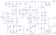
I have upped the LTP current and the VAS current slightly. This is reflected in the change of R27 to 11K and the bootstrap R's to 3.2K.
The updated schematic:
Attachments
PB2 said:What happens to the 20 kHz distortion if you drive the input through a 10 K or 100K ohm resistor?
Pete B.
Imagine that you drive the amp from a passive pre-amp, with say a 20 to 50 K vol pot. The source impedance would be high with the pot in the center of rotation. Not saying that you'd actually do this, but doing the test demonstrates non-linearity of the front end load impedance.
Pete B.
MJL21193 said:
Hi Pete,
Thoughts on the appropriate values for an equivalent RLC circuit for this? My interest in this is high enough to dig deeper.
Let me take a shot at explaining the bootstrap cap here. First consider that the output is, roughly, a low impedance version of the VAS output, since it is a unity gain emitter follower. It follows the VAS output. Now, consider the circuit with no input, the center of R30 and R31 is at half of the negative supply once cap C12 is fully charged. C12 has half of the negative supply voltage across it since the output is at 0 V. C12 and the combination of R30 and R31 have a long time constant since C12 is large. The voltage on C12 doesn't change much at and above midband audio frequencies due to this long time constant. C12 maintains a relatively constant voltage across R30 due to this long time constant, and because the main out follows the VAS output. Constant voltage on a resistor requires constant current since i(t) = v(t)/R. The larger you make C12 the better it will maintain a constant voltage across R30, and to lower frequencies. This is the frequency dependency that I was talking about.
Also, as the main out goes to the negative rail for full output, C12 boosts the voltage to the VAS, remember it is charged to 1/2 the neg supply and ideally ignoring discharge of the cap you would see about 1.5 times the negative supply on fully output negative peaks at the junction or R30, R31, and C12. I suggest that you probe it and drive the amp to full output.
I did this in real hardware as a young kid when I built a copy of the HK Citation 12 ... that was a long time ago ... lol!
The boostrap in a sense provides a high supply voltage, or one that tracks the signal to the VAS, however this only happens for one side of the signal swing, obviously.
Pete B.
Hi Pete,
I did the impedance tests on both versions. The version with the CCS frontend faired considerably worse than the bootstrap version, so I fail to see the point of it. The bootstrapped version held distortion below the 0.001% level.
What I meant when I said RLC was for simulation purposes, to take into accurate account what the detrimental effect of the bootstrap cap is. Considering that I increased resistance and inductance to the point where it didn't resemble any capacitor that you would use for this purpose, I think the effect can be discounted.
What is happening here? Why is the simulation giving me these results if they are not close to actuality? Why am I hearing many different reasons why not to use this current source, only to turn around and run the simulation or the actual operating amp which disproves the reasoning?
- Low frequency distortion: inconsequential.
- PSRR: No hum or buzz from operating amp.
- supply fluctuations: distortion still below the audibility threshold.
- reduced linearity: no evidence of this in any amount that would be audible.
Everyone has their reasons why they would do things differently. Mine are without prejudice, as I haven't formed any of these beliefs yet. When I change something, it needs to be for better results, not to appease the popular opinion.
The series input resistor has nothing to do with the bootstrapped VAS, more to do with the effect of the LTP cascode. Just something else interesting to look at. Is there a difference with and without the resistor for the same output level?
You say that the LF distortion is inconsequential, and as I understand it you mean to _you_. Andy was simply showing that it is higher than at midband to demonstrate a disadvantage of the bootstrap. If none of these things matter to _you_ then go ahead and use the bootstrap if it makes you happy. I don't think any of us expect to change your mind, we are just pointing out the difference because you asked.
Pete B.
PB2 said:You say that the LF distortion is inconsequential, and as I understand it you mean to _you_. Andy was simply showing that it is higher than at midband to demonstrate a disadvantage of the bootstrap.
The strange thing is, he saw an increase in simulated distortion going from 200 Hz to 20 Hz even with the constant current load on the VAS. This makes no sense to me, as the loop gain of the CCL version should be the same or higher at 20 Hz than at 200 Hz. I'm baffled by this.
PB2 said:If none of these things matter to _you_ then go ahead and use the bootstrap if it makes you happy. I don't think any of us expect to change your mind, we are just pointing out the difference because you asked.
Hi Pete,
My post above may come across as aggressive or belligerent, but it was not meant to be.
My point was that I have been presented with several reasons why the bootstrap is not the best solution, and this proves out. Bootstrap is not the best solution.
BUT, it is also not the worst solution. The impression I get is that I am willing to settle for inferior results if I use this and I have shown that to be not the case.
Results are good, better than good in fact. It tests very well in actuality and in simulation. I don't have another simulation model that comes close to how low the overall THD is for this amp. That's great, but what else? Shoot, it's stable and has a high slew rate. It's high power plus it's simple and cheap, without "fancy" components or a parts count in the thousands.
It sounds great.
MJL21193 said:Hi Pete,
I did the impedance tests on both versions. The version with the CCS frontend faired considerably worse than the bootstrap version, so I fail to see the point of it. The bootstrapped version held distortion below the 0.001% level.
Hi John,
I was intrigued by the arguments set forth in this thread regarding bootstrap and CCS. I have an amp designed some time ago with almost identical topology than patchwork using a bootstrap and running the VAS at 7.5 mA.
During the day I took the amp and made some measurements using the bootstrap and then changed to CCS.
I conclude as follows:
At LF the bootstrap is being modulated by the signal. The current variation wass around 4 mA while CCS remained stable.
However current regulation from about 100 Hz the bootstrap performs quite well. Increasing the time constant had marginal effect.
Interestingly, the THD using the CCS revealed almost an order of magnitude increase in the higher odd order harmonics (5th harmonic up.)
Although THD measured higher using the CCS, both younger engineers partaking in the experiment agreed that the CCS amp sounded crisper.
I imagine that it was the higher odd order harmonics accounting for the crisper sound.
I am 50+ and a bit disappointed, because I could hear no difference between the two.
andy_c said:
The strange thing is, he saw an increase in simulated distortion going from 200 Hz to 20 Hz even with the constant current load on the VAS. This makes no sense to me, as the loop gain of the CCL version should be the same or higher at 20 Hz than at 200 Hz. I'm baffled by this.
Here they are. I have my home-brew cap model in effect with the added .2ohm resistor and the 250nH inductor. Bottom CCS, top bootintheassstrapped. 🙂
really, what is the problem here? I don't see one.
Attachments

Nico Ras said:
Interestingly, the THD using the CCS revealed almost an order of magnitude increase in the higher odd order harmonics (5th harmonic up.)
This is exactly what I see in the simulation also. Higher order harmonics are up. Overall higher THD for the CCS.
MJL21193 said:really, what is the problem here? I don't see one.
I don't either. Maybe I misunderstood your earlier post.
andy_c said:
The strange thing is, he saw an increase in simulated distortion going from 200 Hz to 20 Hz even with the constant current load on the VAS. This makes no sense to me, as the loop gain of the CCL version should be the same or higher at 20 Hz than at 200 Hz. I'm baffled by this.
Hi Andy,
your comments were not posted when I typed mine, but I confirm more or less what you write.
Interestingly what I saw on the spectrum analyser was that second harmonic using the bootstrap was pronounced, while the higher order products were more pronounced with the CCS.
However power density over ten measured harmonics for both was much in the same legue, ie. both have about the same THD.
Could this account for a less "crisp" or "warmer" sound of the bootstrap?
andy_c said:
I don't either. Maybe I misunderstood your earlier post.
Hi Andy,
I get confused myself! Too many tests, too many variables.
Do you think my Jerry-rigged model for the bootstrap cap is effectively tricking the simulator to have it react like a real capacitor? I pretty much guessed the values for R and L.
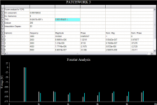
MJL21193 said:
This is exactly what I see in the simulation also. Higher order harmonics are up. Overall higher THD for the CCS.
Here is what I am seeing. This is both topologies at the same input level (600mV).
Base chart is for bootstrapped, white traces.
Aqua traces are the CCS as is the aqua highlighted THD figure.
EDIT: Maybe there is something to the contention that the bootstrapped topology sounds better. 🙂
Attachments
Hi John,
Let me backtrack a bit. Earlier on, I mentioned that the bootstrap circuit should, for a sufficiently low frequency, show a distortion that increases as the frequency goes down. This again being due to the decreasing loop gain as the capacitor impedance rises, along with decreasing load impedance seen by the VAS.
So you did sims of the bootstrap circuit at 20 and 200 Hz, and indeed the 20 Hz distortion was higher than the 200 Hz distortion. This should not happen with a combination of constant current source for the input stage and constant current load for the VAS though. That's why I was baffled. I may have misunderstood your earlier post on this subject. At any rate, you seem committed to the bootstrap configuration, so I guess it's a moot point anyway.
Regarding SPICE models of electrolytic capacitors, Cornell-Dubilier has an app note about that in this PDF file. Here's what they say:
"Typical series inductance values of radial and screw-terminal capacitors are about 1-2 nH/mm terminal spacing. This value does not vary significantly with temperature or frequency, so this portion of the impedance modeling is simple."
- Status
- Not open for further replies.
- Home
- Amplifiers
- Solid State
- Patchwork Reloaded: Circuit Optimization and Board Layout.