homemodder said:Nico,
Do you have connections in JHB?? I know some parts dealers there and wouldnt mind getting my hands on some extra supplies, very cheap, was anyway till I left.
Can I mail you privately??
What a question, of course you can.
Nico
MJL21193 said:Hi David,
Thanks. My bolt holes were pretty precise, location wise and they were slightly oversize. This gave it the flexibility to be put together evenly - I laid it on a flat surface after it was assembled and before it was bolted tight.
I went to town on it with the belt sander driving a 60 grit belt. It's still not as smooth as I want it yet.
I have all of the parts for the other one, just need to put it together.
These are 6" high and 17" long. Hefty.
Hi John,
is it an optical illusion or did you design a curved heat sink to go with the curved speakers?
Hi Nico,
No, not an illusion. The parts were slightly thicker on one side than the other, making the whole construction bowed inwards.
I have since taken it apart to undo this bend (by alternating the pieces). It is now slightly bowed the other way and I may leave it like this and incorporate the curves into the chassis design.
I can mount the semis vertical, three boards per heatsink and and get good contact.
I'm waiting on supplies. I ordered a bunch of blank PC board from a guy on Ebay and I need this to do the boards. Also waiting on the new transistors from Pacific.
This gives me time to work on the board layout, getting it as concise as possible.
The pin out for the 2SA970/2240 is the inconvenient E C B making a mess of things.
Attachments
G.Kleinschmidt said:
Welllll....... I guess it all depends on what one views as complicated. I'd personally occupy my PCB real estate with a pair of BJT's as current sources for the LTP tail and VAS bias over some power resistors and chunky electrolytic capacitors, and reap the much better low frequency PSR.
Hmm, I see my reply was tossed in the trash. Typical. So much for a little light humour.
Glen, my electronical mentor, I don't want to use an active current source on the LTP or the VAS. I like it this way.
Besides, how will you quantify the benefits of better low frequency PSR? A few ticks lower on the THD measurement? Or will this be an audible improvement?
Highly doubtful.
Getting much closer on the board layout. I managed to do it with only 2 jumpers.
Attachments
Hi MJL21193
I see the pcb is coming along nicely, what software you using??
Current sources arent bad, the problem lies with designing a proper one for audio use. Just a plain one made up with led or diodes are not good sounding at all. I experimented a lot with this some years back and like Glen I prefer the 2 transistor one. The trick is to place a resistor between the current source and the LTP emitters. The resistor will isolate the current source capacitance from the LTP and also limit dissapation in it. When done using a low cap high beta tranny you will not hear any difference to a purely resistive source and can have the added benifits of a active source. This is also true of current mirrors.
homemodder said:I see the pcb is coming along nicely, what software you using??
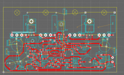
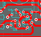
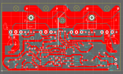
Thanks. Ultiboard.
My goal was to make the layout as compact as possible and as efficient as possible. Notice how the ballast resistors double back over the outputs, putting the output trace at the outside of the board. As much a star ground as possible, with little intrusion on the front end.
homemodder said:
Current sources arent bad, the problem lies with designing a proper one for audio use. Just a plain one made up with led or diodes are not good sounding at all. I experimented a lot with this some years back and like Glen I prefer the 2 transistor one. The trick is to place a resistor between the current source and the LTP emitters. The resistor will isolate the current source capacitance from the LTP and also limit dissapation in it. When done using a low cap high beta tranny you will not hear any difference to a purely resistive source and can have the added benifits of a active source. This is also true of current mirrors.
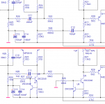
I did some experimentation. I fitted the LTP and VAS with 2 transistor current sources. As shown below, the upper is original and the lower is 4 transistors heavier. The LTP runs at ~4mA and the VAS at ~9mA, nearly identical to the original.
Attachments
Interesting results, I must run this on LTSpice. Ive never used bootstrapped circuit before, maybe I should make some time to measure one but with a scope. The result could be attributed to spice inaccuracy.
Someone here have real measurements???
Using a fancy, I call it optimal vas transistor makes a much huge difference not only measured but also sonically, maybe larger than the bootstrapped case.
What did the amp sound like during listening tests ??? Any better than previous one??
A little tweak you should consider before final PCB layout is to make provision to use some phase lead compensation. After final construction you could experiment a bit using this technique to improve sonics. I think youll find improvement. Just a cap from cap from vas collector back to ltp feedback node, around 10, max 20pf. You could try this in spice. Maybe youll get a bit worse THD figures, but then have a look at phase response. During listening tests is where youll hear the diffrence it makes. You could read some theory about this from JLH and a very good read is TI application note on compensating opamps.
I see Glen has also now used this technique in his latest creation, I wonder if it was for theory or subjective reasons, Glen???
homemodder said:place a resistor between the current source and the LTP emitters. The resistor will isolate the current source capacitance from the LTP and also limit dissipation in it. When done using a low cap high beta tranny you will not hear any difference to a purely resistive source and can have the added benefits of a active source.
but you missed the significance of the series resistors to the CCS collectors. Drop about half the voltage over the resistor.MJL21193 said:I did some experimentation. I fitted the LTP and VAS with 2 transistor current sources. As shown below, the upper is original and the lower is 4 transistors heavier. The LTP runs at ~4mA and the VAS at ~9mA, nearly identical to the original.
Then consider what happens to your carefully set up currents when the mains voltage is 10% low or just as bad 10% high. Active loads are much more tolerant of this variation.
homemodder said:
What did the amp sound like during listening tests ??? Any better than previous one??
I don't think so. I could pretend that I hear a notable difference, but that would be a lie.
The original was a very good, accurate amp and my ears are far from golden.
AndrewT said:
Then consider what happens to your carefully set up currents when the mains voltage is 10% low or just as bad 10% high. Active loads are much more tolerant of this variation.
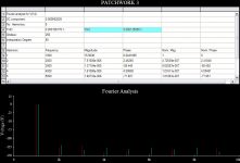
What happens, according to the sim is an increase in distortion - 0.0001% more for a 5V drop and 0.00001% more for a 5V rise.
For 10V up: 0.00006% higher.
For 10V down: 0.0004% higher.
So, running the amp with considerably higher or lower voltage will not have a major impact. Even running a full 20V below speced supply, simulated distortion is still less than 0.001%.
MJL21193 said:Putting PSRR aside, there is nothing to be gained.
My gut feel here is that if you look at 20 Hz, the ratio of THD values between CCS and bootstrap will be similar to what you saw previously when you looked at the bootstrap case at 20 Hz and 200 Hz.
I'm not trying to convince you to do what you do not want to do, just to understand all the tradeoffs.
andy_c said:
My gut feel here is that if you look at 20 Hz, the ratio of THD values between CCS and bootstrap will be similar to what you saw previously when you looked at the bootstrap case at 20 Hz and 200 Hz.
I'm not trying to convince you to do what you do not want to do, just to understand all the tradeoffs.
Hi Andy,
I appreciate your input here. Every time I do a project like this, I learn more and more. This is the painless way, I suppose. At 42 I'm not as easy to "program" as I was at a younger age. All thoughts, observations and comments are welcome. I have a hide as thick and rough as shark skin. 🙂
As to the this VS that, I had been taking that difference into account when I said that - it is not a significant problem to me.
But, I went ahead and ran the distortion at 20Hz for the CCS as opposed to the bootstrap and...no difference. I get the same with both at 20Hz and nearly the same at 200Hz.
The difference, as mentioned before is 0.001% at 20Hz and 0.00002% at 200Hz.
I
John,
Both implementations are forms of current sources, that's why the measure the same midband. Also, you're probably using an ideal SPICE model for the cap, why expect it to show any difference? One difference is that the bootstrap version has a frequency dependency as Andy pointed out. You can simply make the cap bigger to improve the LF distortion, however I prefer the active source as I've state in the past.
Have you restored any older audio equipment?
I have a Hafler DH-110 preamp that I've owned from new. A cap on the output of the transformer failed in the first few years. The electrolytic timing cap failed so that it would not come out of mute. I've changed most of the rest of the electrolytic caps. There are several odd value and package NPEs in the phono section, that are going to be difficult to find replacements for, almost not worth the time. I've built enough equipment that I get no enjoyment out of these repairs.
I also have an Advent 300 Receiver and its mute circuit failed "on" due to a bad electro. Recapped that mainly because I wanted a good working sample of the phono pre. Lots of electros.
I have a Nak BX-300 that I owned from new, it no longer works and my guess is elecrolytic caps.
I like equipment that will work for many, many years without maintenance. Ideally, for me, I like to only have the main large caps to ever replace in a power amp. Just my opinion.
Pete B.
MJL21193 said:
Hmm, I see my reply was tossed in the trash. Typical. So much for a little light humour.
Glen, my electronical mentor, I don't want to use an active current source on the LTP or the VAS. I like it this way.
Besides, how will you quantify the benefits of better low frequency PSR? A few ticks lower on the THD measurement? Or will this be an audible improvement?
Highly doubtful.
Getting much closer on the board layout. I managed to do it with only 2 jumpers.
😀
Less low level bzzzzzz. Just use some big electros for the bootstrap and the rail filter.
Cheers,
Glen
homemodder said:Hi MJL21193
I see the pcb is coming along nicely, what software you using??
Current sources arent bad, the problem lies with designing a proper one for audio use. Just a plain one made up with led or diodes are not good sounding at all. I experimented a lot with this some years back and like Glen I prefer the 2 transistor one. The trick is to place a resistor between the current source and the LTP emitters. The resistor will isolate the current source capacitance from the LTP and also limit dissapation in it. When done using a low cap high beta tranny you will not hear any difference to a purely resistive source and can have the added benifits of a active source. This is also true of current mirrors.
Hmm.
The only reason to putting a resistor between the current source and the LTP emitters is to limit the dissipation in the current source transistor. It will not isolate the LTP emitters from the current source capacitance in any meaningfull way whatsoever.
The same common mode AC signal will exist on the collector of the current source transistor, resistor or no resistor and the same AC currents will flow through the capacitances.
If anything the effects of the b-c capacitance of current source will be greater with the resistor and the c-e voltage is lower, making Cob bigger.
I don't think there is anything wrong with LED biased current source with a single transistor either, especially WRT its "sound".
Cheers,
Glen
homemodder said:Hi MJL21193
I see the pcb is coming along nicely, what software you using??
Current sources arent bad, the problem lies with designing a proper one for audio use. Just a plain one made up with led or diodes are not good sounding at all. I experimented a lot with this some years back and like Glen I prefer the 2 transistor one. The trick is to place a resistor between the current source and the LTP emitters. The resistor will isolate the current source capacitance from the LTP and also limit dissapation in it. When done using a low cap high beta tranny you will not hear any difference to a purely resistive source and can have the added benifits of a active source. This is also true of current mirrors.
Hmm.
The only reason for putting a resistor between the current source and the LTP emitters is to limit the dissipation in the current source transistor. It will not isolate the LTP emitters from the current source capacitance in any meaningfull way whatsoever.
The same common mode AC signal will exist on the collector of the current source transistor, resistor or no resistor and the same AC currents will flow through the capacitances.
If anything the effects of the b-c capacitance of the current source transistor will be greater with the resistor as the c-e voltage is lower, making Cob bigger.
I don't think there is anything wrong with a LED biased current source with a single transistor either, especially WRT its "sound".
Cheers,
Glen
EDIT; typos
Hi John,
I have been reading our fellow members opinions with interest and I also have been a bootstrap fan for many years, but what they are saying makes absolute sense.
Besides I have looked at the capacitance models and although simulators have an option of defining models for capacitance, in standard form they are pure capacitors and a simulation will not reveal the frequency dependability of these parts.
At HF the large electrolytic caps do reveal inductive properties so maybe bypass it with some 10nF polypropylene type. This may also be true for the cap in the NFB leg to ground.
Nico
Glen you might want to read national application note A with regards to the capacitance isolation effect. The source capacitance affects slewrate too.
Resistors have inductance which will tend to block the ac signal, better to use 2 resistors in fact.
True about the cob but I have just had a look at the transistor I usually use datasheet and the raise cob would have If I had to drop say like Andrew mentioned half the voltage accross it, I would consider it meaningless, less than 1pf for worse case.
Maybe the isolation is more meaningfull than it appears. This could be calculated, Glen you up for it??
MJL21193 small diffrences are difficult for me to hear too, I use seinheisers to do that now or ask a friend or relative which doesnt know the diffrence between a resistor or a BJT but a lot about music.
PB2 said:
Both implementations are forms of current sources, that's why the measure the same midband. Also, you're probably using an ideal SPICE model for the cap, why expect it to show any difference?
Hi Pete,
Thoughts on the appropriate values for an equivalent RLC circuit for this? My interest in this is high enough to dig deeper.
PB2 said:
Have you restored any older audio equipment?
I like equipment that will work for many, many years without maintenance. Ideally, for me, I like to only have the main large caps to ever replace in a power amp. Just my opinion.
I have a Pioneer SA-6800 from the early 80's that still works just fine. It's filled to the brim with electrolytics. It's not from the gentle treatment it has had either. 🙂
G.Kleinschmidt said:
Less low level bzzzzzz. Just use some big electros for the bootstrap and the rail filter.
No buzzz Glen. Complete and utter silence.
Imagine, struck down for using the words, in a quote, "sexual intercourse". Fracking pre-school here.
- Status
- Not open for further replies.
- Home
- Amplifiers
- Solid State
- Patchwork Reloaded: Circuit Optimization and Board Layout.