Noise and bandwith theory originates from thermal noise from a resistor. E=7.43√R⋅T⋅ΔF.Somehow I though noise would be about constant no matter frequency, is there different kind of noises?😀 I guess the total would drop as bandwidth is reduced, hmm, is it because there is more power in music in lows that makes the difference or whats the relationship? sorry I don't know too much about amplifiers... just trying to make sense of it, why noise drops more than "content" 🙂
Rs in amps is normaly not changable
T is what it is in the amp.
deltaF is bandwith of the amp.
The bandwith seen by the woofer can be changed by passive components outside the amp.
So the good practice noisewise is to limit the bandwith of the amp to the signal bandwith.
Then you only get noise in the so called passband and not noise with frequencies outside the passband.
Actually you also have to consider the transfer function (frequency responce) of the speaker element so se how much noise is attunated.
Another field where one can be fooled by noise and bandwith is SINAD. High bandwith DACS has bad SINAD compared to low bandwith DACS. But if filtered, the high bandwith DAC actually can have better SINAD.
But if the noise is masked or under hearing threshold, don't bother.
So again, mostly for hi inch broadband drivers with 10+ dB response in mid and one only wan't to use the bandwith of bassnotes for that driver
Example of driver that could be bandwith limited.
https://en.toutlehautparleur.com/media/catalog/product/datasheet/audax/PR380M2-8.pdf
I have this myself and it generates guite a lot of hiss if not passivly filtered at lets say 500 Hz
https://en.toutlehautparleur.com/media/catalog/product/datasheet/audax/PR380M2-8.pdf
I have this myself and it generates guite a lot of hiss if not passivly filtered at lets say 500 Hz
Shows how little energy goes into the tweeter in home use. Crest factor in HF part of the music is most often large so low average energy (heat in resistor)I am using it in an active, DSP crossover based loudspeaker (as I stated earlier), so it's not passive.
The 10W resistor (a normal one, without heatsink) was never even lukewarm in home environment. I check it regularly, because it's placed outside of the speaker enclosure, easily accessible for the fingers.
But top values in the waveform could be high so god to have lot of headroom in the amp. maybe 1 to 10 of max power compared tolong term power into speaker element.
And you could still use a LC filter to protect it. Under Fs the cone movement is quadruppled for each octave. So not much bass noise or DC is needed to create unessesary cone movement that increase the distortion. And for cone movement it is top value that counts, not average value (Noise is most often given as an average value. But it is gaussian so also has som much larger peaks)
I have used sine-cap filter for my SS6600 for some years now. A 6.8 Ohm 30W resistor in serie and a 0.12 mH inductor in paralell. I like it alot, moore people sould try it.I am using a "sine-cap" passive filter for the CD+horn instead of L-pad+capacitor in a DSP crossover system. This consists a series resistor followed by an inductor to the ground, same as the Sonus Faber used in the Extrema's crossover. The filter is similar to a first order filter and an attenuator, but it damps well the resonance peak of the driver and can compensate the sloping down horn response and you have only a single resistor in the signal path without a capacitor. But be aware, the sine-cap filter actually is a shelf filter, it won't blocks DC, but can reduce it's level (if present).
Hi all,
some data @b_force is likely interested.
I've got Faital Pro 8pr155 midrange driver in an active speaker system and it has quite severe cone breakup peak around 4.5kHz. This makes peak in harmonic distortion measurement, because distortion from driver motor makes lot of distortion current in an active system as circuit impedance is very low due to very low impedance amplifier and no passive components to increase the impedance, further amplified by the breakup.
Adding series impedance, a notch filter or just low pass inductor increases circuit impedance reducing effect to current from Le(x), which reduces acoustic distortion as current means movement of the cone.
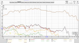
See third harmonic peaking at ~1.48kHz, which is root for 3rd order harmonic at cone resonance 4.5kHz. About -40db relative level.
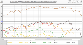
Increaseing circuit impedance with 1mH inductor in series drops this considerably, although signal level is also dropped it can be boosted back with DSP.
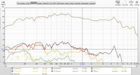
I tried series notch filter as well, but the effect is better with series coil in this use case. Here image illustrating impedance in series with the driver in case of series inductor making 1st order low pass, or just a parallel notch filter.
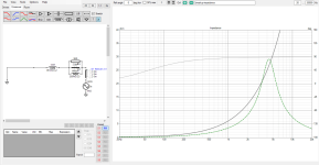
The series inductor increases circuit impedance from few hundred hertz up reducing current by motor distortion, which reduces distortion in acoustic domain as current is what makes the cone move 😉
This kind of crossover, where there is passive parts to manipulate circuit impedance for distortion reduction and DSP to manipulate frequency response independently, is great. Although, I'm not sure if I actually hear any difference between these in normal use.
Forgot to take audio recording of the two, have to do it some day. Also, should have taken measurement with DSP low pass for comparison. Well, can't have everything with hurry 😀
edit. Had very long post, cut most of it out.
some data @b_force is likely interested.
I've got Faital Pro 8pr155 midrange driver in an active speaker system and it has quite severe cone breakup peak around 4.5kHz. This makes peak in harmonic distortion measurement, because distortion from driver motor makes lot of distortion current in an active system as circuit impedance is very low due to very low impedance amplifier and no passive components to increase the impedance, further amplified by the breakup.
Adding series impedance, a notch filter or just low pass inductor increases circuit impedance reducing effect to current from Le(x), which reduces acoustic distortion as current means movement of the cone.
See third harmonic peaking at ~1.48kHz, which is root for 3rd order harmonic at cone resonance 4.5kHz. About -40db relative level.

Increaseing circuit impedance with 1mH inductor in series drops this considerably, although signal level is also dropped it can be boosted back with DSP.

I tried series notch filter as well, but the effect is better with series coil in this use case. Here image illustrating impedance in series with the driver in case of series inductor making 1st order low pass, or just a parallel notch filter.

The series inductor increases circuit impedance from few hundred hertz up reducing current by motor distortion, which reduces distortion in acoustic domain as current is what makes the cone move 😉
This kind of crossover, where there is passive parts to manipulate circuit impedance for distortion reduction and DSP to manipulate frequency response independently, is great. Although, I'm not sure if I actually hear any difference between these in normal use.
Forgot to take audio recording of the two, have to do it some day. Also, should have taken measurement with DSP low pass for comparison. Well, can't have everything with hurry 😀
edit. Had very long post, cut most of it out.
Last edited:
@tmuikku
Do you have the distortion in relative numbers, either % (Ideally) or otherwise relative dB's?
And yeah I wanna see a comparison with DSP. 🙂
Edit: a quick count suggests an improvement from roughly -35dB to about -50dB at that peak.
Or from 1.8% to 0.32%
That's the 2nd harmonic btw.
Do you have the distortion in relative numbers, either % (Ideally) or otherwise relative dB's?
And yeah I wanna see a comparison with DSP. 🙂
Edit: a quick count suggests an improvement from roughly -35dB to about -50dB at that peak.
Or from 1.8% to 0.32%
That's the 2nd harmonic btw.
Last edited:
Hi,
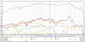
relative numbers are visible on the bottom of the screenshots at cursor frequency ~1.5kHz.
2nd and 4th order distortion drops about 6db, perhaps because excursion is less with the low pass, 3rd order drops about 13db so benefits most from the series impedance.
I'll measure with DSP filter as well some day, plan to do some multitone measurement as well. Had only short time window to do some measurements, made these at the end without planning beforehand so kind of second thought.
edit. I can't find how to normalize the graph to show the distortion relative to signal. Here the numbers in percent, shown bottom of the images:


Last edited:
Hi tmuikku, can you boost the signal of the 1mH inductor to match up the without?
Drive level dominates too much in comparisons not to, i think
This is how I use passive in active systems.....as an easy way to lower amp channel count needed.I think hybrid designs are useful for adding a fourth driver to a three channel DSP system. If you had woofer, mid woofer, midrange and tweeter. The midrange and tweeter crossover could be passive, as those components are small and cheap. If you are using transconductance amplifiers, that passive crossover would be a series crossover. I don't think a properly designed active system can be matched in performance by a system with passive crossover components.
I have some speakers with toggle switches in them, to put the higher frequencies passive crossover in or out, depending on amp channels available.
If I have the channels, I always go fully active.
Hi,
didn't have time / forgot to do it but I'll do some day 🙂 There is 10db difference in signal level, so it must contribute some to the distortion, equalizing with DSP to match the responses with or without inductor would show more accurately change in distortion.
This driver is in use in loudspeaker system with the series inductor and EQ:d with DSP for suitable system response. Bandwidth for the driver is roughly 200-1300kHz, and as you see level around 200Hz is same with or without the inductor. Inductor drops the response to the same level around 1.3kHz so there is no need to boost with DSP in real application, only cut in either case so basically the distortion reduction here is free in that sense. Or, perhaps 5€ worth of inductor to be precise 😀
Last edited:
At the breakup frequency, the SPL is more than 12 dB more without the inductor, that's a lot. A fair comparison would be if the SPLs are the same.
Yeah I need to revisit, the driver with response like in the system, with or without inductor EQualized with DSP to very close each other.
If you compare to say 2nd order harmonic, which drops about 6db, likely due to 10db less output. Same for 4th order harmonic. 3rd order relatively more, ~13db. In general, 3rd order drops relative to 2nd order harmonic from about 400Hz and up.
If you compare to say 2nd order harmonic, which drops about 6db, likely due to 10db less output. Same for 4th order harmonic. 3rd order relatively more, ~13db. In general, 3rd order drops relative to 2nd order harmonic from about 400Hz and up.
Last edited:
Well in the end it's about the impedance.as its low pass and not a notch
Given that the impedance of a full notch is A LOT higher, an inductor should still do at least something.
But that could fall within measuring error.
It's hard to tell at this point, since there are other variables at play as well.
Ok, sent family to library for a second so could take measurements 😀
These are with in application setting to the extent speaker was where it is normally installed, just muted tweeter and woofer in DSP. This is with coil.
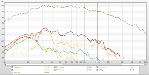
Popped it open, shorted the coil and adjusted DSP to match quite closely to the coiled response, as closely as could in few minutes, it's about within 1dB. So, this is without coil with roughly application frequency response.
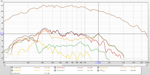
Here is match, 1/6th octave smoothing:
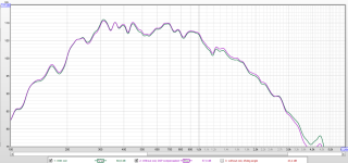
Here is multitone measurement with both as well, individually and overlaid;
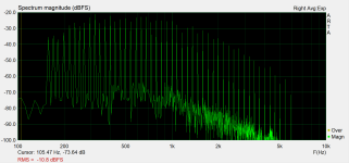
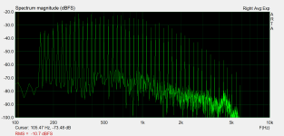
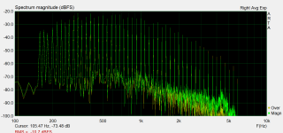
And as bonus for @b_force here is mic moved to about 45deg angle, this is without coil. Notice how the breakup peaks are gone/different, also from distortion! 😉
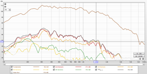
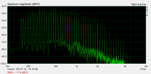
These are with in application setting to the extent speaker was where it is normally installed, just muted tweeter and woofer in DSP. This is with coil.

Popped it open, shorted the coil and adjusted DSP to match quite closely to the coiled response, as closely as could in few minutes, it's about within 1dB. So, this is without coil with roughly application frequency response.

Here is match, 1/6th octave smoothing:

Here is multitone measurement with both as well, individually and overlaid;


And as bonus for @b_force here is mic moved to about 45deg angle, this is without coil. Notice how the breakup peaks are gone/different, also from distortion! 😉


Well, ..... the plot thickens .... 🤔
I see a lot more than just only break-up peak going down?
Without coil you mean, no notch?
I see a lot more than just only break-up peak going down?
Sorry, I don't totally follow this?here is mic moved to about 45deg angle, this is without coil. Notice how the breakup peaks are gone/different, also from distortion!
Without coil you mean, no notch?
Wow, great result on the 3rd and even the 5th HD did reduced significantly, just by a coil, multitone distortion are lower too!
Without the single series coil, I think.Without coil you mean, no notch?
Yeah, there is no notch filter in the setup, only series coil. That is why distortion drops everywhere where series impedance is increased, basically almost the whole bandwidth in this case.
The 45deg set is without coil as well, you can compare that to the on-axis no coil graph. Point was to illustrate that the breakup is amplifying the distortion in acoustic domain, on-axis mostly. Off axis could have reduction in distortion, what ever the erratic output due to break up is to various directions with various drivers.
The 45deg set is without coil as well, you can compare that to the on-axis no coil graph. Point was to illustrate that the breakup is amplifying the distortion in acoustic domain, on-axis mostly. Off axis could have reduction in distortion, what ever the erratic output due to break up is to various directions with various drivers.
- Home
- Loudspeakers
- Multi-Way
- Passive crossover parts in active speaker system? Possibilities of hybrid crossover

