You seem to be saying that the impedance and the backEMF are not the same thing?not due to what happens to back EMF but how much current goes through the driver
back EMF is voltage source within the driver: as cone moves the voice coil moves inside magnetic field and voltage is induced to the coil. Basic stuff you should know this. Impedance is just relationship of voltage and current at some particular frequency, its not same thing as back EMF, although back EMF is what makes the circuit impedance at driver resonance if you measure driver inputs ~shorted 😀 Not sure what are you after?
Between back EMF and impedance? I don't know what you mean by overthinking, understanding the system in practical level so that I can fully utilize circuit impedance to my advantage what ever the system is at hand?😀 You can think it simply or complicated, it's fine as long as you can utilize it to your advantage what ever the system is at your hand.
Pardon if my explanation over this seems complicated, but it's not exactly simple subject and I'm not teacher and not aware of any material that would sum this all up in loudspeaker context in simple form. Trying my best 🙂
Pardon if my explanation over this seems complicated, but it's not exactly simple subject and I'm not teacher and not aware of any material that would sum this all up in loudspeaker context in simple form. Trying my best 🙂
Last edited:
Esa's article I posted earlier has nice image about what driver impedance is made of. Three main parts: resistance of the voice coil (wire), inductance of the coil and motional impedance at the resonance.
Impedance is literally Z=U/I: when you put constant voltage over a load and measure current and plot their relationship you get impedance plot. Now, what the high impedance peak means at resonance? It means that there seems to be less current with the input voltage than at some other frequency, like for example octave above the resonance.
Why is that? Since at the resonance the driver resonates obviously, moves very easily as suspension and mass of moving parts are at equilibrium, the system resonates, like a pendulum. This means, that very little current at resonant frequency makes enough force in the motor to send the cone to relatively huge excursion, which means there is relatively big back EMF voltage compared to the input current that set the motion. The relatively big back EMF makes relatively big current over the low circuit impedance, current that opposes the movement. Now, sum this opposing current with the initial current and you'd measure total current with your current meter, and plot high impedance because the current seems less than octave above 😉 It's not magic, no need to overthink. In this case,the impedance peak is due to back EMF making opposing current, which you'd measure as "less current", so high impedance as we use constant voltage to measure.
Clamp the cone still and measure impedance, and the peak reduces. Or add damping material inside enclosure to add mechanical damping. What this means is the same voltage sent the cone to huge excursion previously, doesn't as much anymore due to extra damping, which makes less movement with given input current, less back EMF voltage, reduced opposing current so higher current as total, and you see reduced impedance peak.
As per Esa's article, the back EMF happens at all frequencies depending on the motion, but it is relatively less because more current is needed for excursion on any other frequency than around main resonance. Also, due to acceleration of mass above resonance, the back EMF generated current is not opposing phase and does not cause too much reduced current, big impedance peaks. The impedance plot defines what Esa writes, or vice versa, it's good information well worth reading repeatedly.
Last edited:
Here is the article again:
https://www.edn.com/loudspeaker-operation-the-superiority-of-current-drive-over-voltage-drive/
What I'm trying to do is to explain the same thing without maths and emotion towards amplifier topologies.
I'm trying to write about it how I undestand it and what feels intuitive way to think how the stuff works to me. Not sure how you'd imagine /picture the stuff yourself or how I could explain it more clearly.
I keep on writing / commenting about it as it doesn't seem to be very well understood, in general, how it plays out.
Perhaps it is well understood and I'm not getting it 😀
Doesn't matter to me though, I can utilize it in my system successfully without confusion, can come up with simulations and measurements to verify which means I have enough understanding for practical use. I do not know what actually happens in very detailed scientific level, of course, because I'm a hobbyist and need to know only so much that's useful to me.
I hope these posts answered your question? I wish I knew everyone of you better to be able to explain it as understandable as possible. Happy to answer questions, it's fun, although starts to feel like going in circles 😀
Last edited:
Very much yes lol 😀 😀it's fun, although starts to feel like going in circles 😀
Well, I have a good grasp of it, but some early comments (I think it was Risbo) just don't make any sense of it when we talked about the constant current source.
In fact, it pretty much is very similar to Power Factor Correction.
Which has very similar distortion issues (just not in audio obviously).
But the underlying Back EMF problems are very similar.
What makes it all very hard to understand clearly, is that most papers and articles only focus on one small piece OR (worse) look at is from the perspective of driving just one single loudspeaker with it (incl around Fs).
Offtopic, (although related), I don't see ANY benefits of doing everything by one speaker.
- More cone excursion WILL introduce nonlinearities like Le(x) etc etc etc.
- Cannot fix room modes like a multi sub-system can do.
- Quickly needs a BR approach, which always has speaker backwave issues + an additional resonance (standing wave) of the port.
- This resonance is often around 500-1500Hz, which is just very nasty and audible.
- BR systems are a lot less predictable.
- The higher frequency part is often very erratic.
(btw, I am also NOT saying you can't make a nice sounding system)
There are a few exceptions, like a nice (mini) line array with some 3-4inch full-range drivers.
Although it's hard to find ones that perform well from around 120Hz.
Especially the emotion part I really hope more people can pick that up.What I'm trying to do is to explain the same thing without maths and emotion towards amplifier topologies.
I personally wouldn't care less if we can fix it all with just some duct-tape.
I only care about the end-result but most importantly, the practicality of it.
Like Erin said super well in his latest video, there is NO best solution.
It's all about finding the right compromises.
Even if a constant current amplifier would have some nice benefits, the biggest hurdle is still implementing it on a practical way.
Which reminds me of, the frequency part is pretty easy to simulate in LTSpice 🙂

Yeah, understanding, or bringing it all together pretty much requires understanding what the impedance is, and that current makes acoustic sound, and so on, then some head scratching and playing with simulator in addition to reading some of the material to help thinking about it. After figuring it out passive crossovers come easy to figure out, and so on, it's whole electrical domain of loudspeakers that is involved, including some if the mechanical stuff.What makes it all very hard to understand clearly, is that most papers and articles only focus on one small piece OR (worse) look at is from the perspective of driving just one single loudspeaker with it (incl around Fs).
Yeah, what ever makes good sound, if you are after good sound in the first place 😀 And the better you know what the context is, what you like, how room effects, how everything interacts, how much there is resources and so on, the better you can optimize for the particular context. Basically, the better the situation is known the better set of compromises you can take, which should lead best possible set of compromises and thus best possible outcome for what ever is it you were after. Not knowing much, or falling into marketing trap, it's easy to take compromises that take away some of the performance.Like Erin said super well in his latest video, there is NO best solution.
It's all about finding the right compromises.
Even if a constant current amplifier would have some nice benefits, the biggest hurdle is still implementing it on a practical way.
Which reminds me of, the frequency part is pretty easy to simulate in LTSpice 🙂
But, for someone else it could be something else, perhaps the audio quality isn't even that important if motivation is just to build something and have fun building, and listen something, what ever. Context before all. Without knowing what is it that you are doing, or supposed to be doing, all bets are off.
I have no feelings toward the technology, I'd like it all to disappear and just have good sound without seeing or tinkering with it at all 🙂 Current state of hobby is to figure this stuff out, what I like, how to listen, how to get best possible sound with practical situation I'm at and so on.
Last edited:
I even enjoy just so many things, that I sometimes like to go as far back as just listening to a (very) old tube radio.But, for some one else it could be something else, perhaps the audio quality isn't even that important if motivation is just to build something and have fun building, and listen something, what ever. Context before all, without knowing it all bets are off.
Is it perfect sound reproduction? Very obviously no.
But it brings a certain, feel, vibe and nostalgia with it.
It's also absolutely fascinating how quickly your brain fills in the gaps and starts to mask as well.
After listening for a while, certain distortion (which is extremely obvious at the beginning) just kinda vanishes.
It's obviously still there, but you actively have to refocus to really notice it again.
Anyway, this is also the reason why I think it's important to understand these things.
Instead of kinda "hoping" all goes well, you are the one in control to make certain decisions and compromises in a system.
Especially people like Erin have totally convinced me that everything is measurable and can be explained, the correlation is right there.
Just not a lot of people have done such objective comparisons and quickly blame it on lack of explanation.
While it is mostly just lack of knowledge and understanding instead.
I say that objectively, not as an offensive thing.
Anyway, enough philosophy.
I have fired up LTSpice and the simulation works super well.
It immediately brings up a very major problem with a constant current source.
The frequency response, or rather output power at a give frequency, is now directly proportional to the impedance.
(a constant voltage source doesn't have this issue)
So this means that the freq resp will be super heavily dependent on how stable the impedance is.
Even a slight difference in impedance, will change the freq resp drastically.
If we just only look at if from above Fs, this means you either have to use a speaker with a very stable Le(x), and/or really have to make sure that there won't be any cone excursion at all.
Which leads to another problem, that is when the voice coil heats up and therefor raises Re.
It's also very problematic with ANY other nonlinear (cabinet) resonances or other issues that reflect back to the impedance.
Or any other tolerances in like components (crossover filters, resistors, capacitors, inductors).
So to very quickly debunk the idea of "why nobody is doing this, it is perfect".
This makes implementing a loudspeaker system extremely complicated even from a practical point of view.
A constant voltage source does makes an awful more sense here, its so much more robust from a practical sense.
I will show some screenshorts later. 🙂
Last edited:
^^ Yeah, I'm currently figuring out how to connect graphs to perceived sound. Like the series coil test yesterday, trying to figure out magnitude of things, how audible stuff is, and so on.
I mean, all the information floats around and is available, for example the CTA 2034 stuff, but it's really hard to tell how any of it actually sounds like 😀 What is good and what is bad and how big difference there is. Then, is it good or bad for what I want to achieve, what is it that I want to achieve and so on, how my room affects. Really fundamental basic stuff, which is often dismissed, at least I have.
Most threads start with "Bought these brand drivers and here is the plan for two way", how backwards is that?😀 well, perhaps they have it all figured out already to come up with the plan that fulfils a purpose, but just not telling no-one about it. There is very rarely any information about the context where they are going to be put. Or, if there is it's very hard to figure out how it would relate to sound since my situation is likely very different.
Well, anyway, each on their own path doing what ever they feel like and that's fine 🙂
ps. the philosophy part is very much fun and big part of my hobby!😀 and reasoning about stuff.
@tmuikku
It does makes me wonder something else.
Something I noticed after looking at distortion plots for some many years.
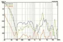
I have noticed that often (but not always), the distortion with 8 ohm woofers is lower than the 4 ohm variant at the same SPL.
Here is a good example with a Dayton RS225 4ohm vs 8ohm @ 90dB
With the same magnet structure, it's a little hard to compare, since they have to wind the voice coil one a different way.
So therefore the parameters change a bit.
But an obvious difference is the inductance @ 1kHz, which is 0.49mH for the 4ohm version and 0.86mH for the 8 ohm version.
Look at that peak around 2900Hz completely disappearing!
It does makes me wonder something else.
Something I noticed after looking at distortion plots for some many years.
I have noticed that often (but not always), the distortion with 8 ohm woofers is lower than the 4 ohm variant at the same SPL.
Here is a good example with a Dayton RS225 4ohm vs 8ohm @ 90dB
With the same magnet structure, it's a little hard to compare, since they have to wind the voice coil one a different way.
So therefore the parameters change a bit.
But an obvious difference is the inductance @ 1kHz, which is 0.49mH for the 4ohm version and 0.86mH for the 8 ohm version.
Look at that peak around 2900Hz completely disappearing!
Attachments
Just a few coments on current source and back EMF.
I see in this forum some very good cone -accellerometer - current poweramp feedback systems has been made.
In 3 phase motors there are current and voltage from the driver on only 1-2 of the phases. Often the phase that is «off» is used to measure back EMF.
Back EMF is also exploited in sub designs to alow big voltage swing without the corresponding current draw and corresponding heat from a more broadband system
Feedback based on cone excursion is quite different than a constant current amplifier.
Once again, constant current amplification does NOT work well around Fs.
Once again, constant current amplification does NOT work well around Fs.
Hi, I can only imagine what it takes to make drivers. Must be a lot of interesting compromises there as well, solutions to choose and decisions to make 🙂@tmuikku
It does makes me wonder something else.
Something I noticed after looking at distortion plots for some many years.
I have noticed that often (but not always), the distortion with 8 ohm woofers is lower than the 4 ohm variant at the same SPL.
Here is a good example with a Dayton RS225 4ohm vs 8ohm @ 90dB
With the same magnet structure, it's a little hard to compare, since they have to wind the voice coil one a different way.
So therefore the parameters change a bit.
But an obvious difference is the inductance @ 1kHz, which is 0.49mH for the 4ohm version and 0.86mH for the 8 ohm version.
Look at that peak around 2900Hz completely disappearing!
If motor is same and only winding was different, higher impedance means more turns, perhaps different wire. Assuming it is just more turns it must fit into the same gap and former so I'd imagine the winding must be longer or something, or perhaps its height is same but the other is somehow more loosely wound. Assuming it was mostly the Le(x) making difference in distortion, so likely Le(x) curve would look different for both. I really have no clue 😀 Perhaps Le(x) is maintained but it's proportionally more with the 4ohm version making more variance to it, more distortion in general.
Higher impedance version there is longer wire in the gap, so more force with same current?
What ever it is, I could think that there is some trend as you have observed. Perhaps manufacturers want to have frequency response similar between the two models, and to keep that something else must give and it might be that the distortion performance is "sacrificed" for it, or something. Well, just speculating.
Current in voice coil makes force to move the cone, which makes acoustic sound. If you keep constant current at some frequency the acoustic output should stay constant as well, right?Anyway, enough philosophy.
I have fired up LTSpice and the simulation works super well.
It immediately brings up a very major problem with a constant current source.
The frequency response, or rather output power at a give frequency, is now directly proportional to the impedance.
(a constant voltage source doesn't have this issue)
So this means that the freq resp will be super heavily dependent on how stable the impedance is.
Even a slight difference in impedance, will change the freq resp drastically.
If we just only look at if from above Fs, this means you either have to use a speaker with a very stable Le(x), and/or really have to make sure that there won't be any cone excursion at all.
Which leads to another problem, that is when the voice coil heats up and therefor raises Re.
It's also very problematic with ANY other nonlinear (cabinet) resonances or other issues that reflect back to the impedance.
Or any other tolerances in like components (crossover filters, resistors, capacitors, inductors).
So to very quickly debunk the idea of "why nobody is doing this, it is perfect".
This makes implementing a loudspeaker system extremely complicated even from a practical point of view.
A constant voltage source does makes an awful more sense here, its so much more robust from a practical sense.
I will show some screenshorts later. 🙂
If you have constant current source the current ought to be constant, and force in the motor constant no matter Le(x), impedance of the driver doesn't make any difference to the current or acoustic output. Also rise in Re doesn't matter until thermal runaway breaks the voice coil open.
You are right that if you have say 100ma current through out full bandwidth the frequency response would vary according to driver impedance because the driver is likely made for voltage amplifier use to give flat acoustic response with varying current. Thus, you must equalize the current somehow, vary it like it would vary with constant voltage amp.
Last edited:
I think one could make a motor for current drive, by leaving iron pole out!? iron pole is there to make Le high with low amount of winding, Le high to equalize the rising high frequency response to flat and also give stronger magnetic field with low amount of coil, to keep impedance down? Frequency response would rise otherwise, as volume displacement stays the same while wavelength drops, so efficiency goes up, right?
But, if you want current drive situation, impedance high, then the iron pole is left out to equalize the hf to other direction by reducing Le. Now just turn more wire to restore some force and drive Re up. I guess power handling would be poorer, and quite likely not this simple, but perhaps this is the core idea?
But, if you want current drive situation, impedance high, then the iron pole is left out to equalize the hf to other direction by reducing Le. Now just turn more wire to restore some force and drive Re up. I guess power handling would be poorer, and quite likely not this simple, but perhaps this is the core idea?
I don't think you completely grasp what a constant current source does.Current in voice coil makes force to move the cone, which makes acoustic sound. If you keep constant current at some frequency the acoustic output should stay constant as well, right?
If you have constant current source the current ought to be constant, and force in the motor constant no matter Le(x), impedance of the driver doesn't make any difference to the current or acoustic output. Also rise in Re doesn't matter until thermal runaway breaks the voice coil open.
You are right that if you have say 100ma current through out full bandwidth the frequency response would vary according to driver impedance because the driver is likely made for voltage amplifier use to give flat acoustic response with varying current. Thus, you must equalize the current somehow, vary it like it would vary with constant voltage amp.
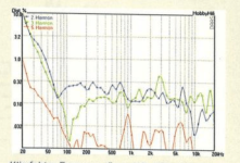
Even if we don't use it with a speaker, the output now all of a sudden depends on the impedance (resistance) of the load.
This is also the reason why a constant current source doesn't work around Fs, because the impedance is super high, resulting in a huge peak at the frequency response.
(red = CC, black = CV)
This is also exactly described in other sources like Voice Coil Magazine.
see: https://audioxpress.com/article/current-driving-of-loudspeakers-book-review
So as soon as the impedance changes (look at impedance graph), the frequency response will change with it.
This will result in some potential problems actually.
Not only the freq resp changes drastically with every little change in the impedance.
It also has a tendency to do potentially destructive runaway behavior.
As soon things warm up, Re will rise, which rises the output more, which warms up the Re up more etc etc etc.
uh?I think one could make a motor for current drive, by leaving iron pole out!?
Any motor works basically the same way, so that doesn't make any sense.
You will always need an (voice) coil that automatically provides inductance as well as a dc resistance.
The DC resistance varies with temperature, the coil inductance changes with cone excursion (or where it is in the field rather).
Thermal runaway is true, because heat makes resistance to rise which with constant voltage situation would reduce current and reduce heat. With constant current this regulation doesn't happen, current would stay constant and keep heating it up, voltage would vary.
Perhaps we are taking different thing? by definition, constant current is constant current isn't it? Impedance is Z=U/I, if you make I constant at some frequency, Z varies as per driver excursion then voltage varies. But voltage doesn't affect acoustic output, only current does, keeping current constant acoustic output stays constant. Le(x) would vary voltage, but it would not make any change in acoustic output.
Problem of varying impedance is problem with constant voltage amplifier, where varying impedance varies current, so acoustic output varies.
Last edited:
- Home
- Loudspeakers
- Multi-Way
- Passive crossover parts in active speaker system? Possibilities of hybrid crossover