More over does T pad have lower or higher impedance for the driver, or is it freely adjustable? If it can be tuned to show ~8ohms for amplifier to see and say ~1ohm for driver to see, then that would make very good damping for the driver without giving hard impedance for the amplifier while still be able to adjust attenuation of the pad separately? Hmm, seems logical, assuming the train of thought correlates with reality 😀
In L-pad all is interrelated as shunt resistor gets lower the more attenuation there is, if amplifier load is kept constant, so more attenuation on the L-pad the better damping for compression driver resonance (as the shunt now has lower impedance). for this reason the T pad performs better in comparison, providing better damping even at low attenuation?
In L-pad all is interrelated as shunt resistor gets lower the more attenuation there is, if amplifier load is kept constant, so more attenuation on the L-pad the better damping for compression driver resonance (as the shunt now has lower impedance). for this reason the T pad performs better in comparison, providing better damping even at low attenuation?


Yeah I think I got this, thanks!Basically yes, but I think you can also get the same effect as you mentioned with the cap on the woofer. I have only scratched the surface by simulating it and correcting it when doing passive XO's.
Basically, drivers as mechanical devices like to resonate. Low impedance on amplifier output allows the driver to see low impedance and the resonance is damped (because terminals are connected and the electronic properties of the driver does not let the mechanical parts move, resists movement). Unless, we have components between the amplifier and driver taking out this low impedance path (at resonance), which then allows the mechanical resonance to continue, there is no (strong) electrical connection between terminals on the frequency to prevent the movement (resonance). Damping factor, alright, starts to make sense 🙂
So, large capacitor in series with woofer (in a sealed box) makes high impedance for the woofers resonance letting the woofer ring for longer giving "boost" on frequency response, capacitor prevents small amplifier output impedance damping the resonance.
edit. tried to simulate this but have no proper data to do so. VituixCAD demo project kontiainen has reflex box and it doesn't seem to play out like so, peak (cap interaction) emerges even though impedance stays about the same at the peak frequency, which is bit off from impedance peaks. I have no idea what would make this, but it looks something that does not seem to correlate with the train of thought in few of my last posts. Well, interesting stuff anyway 🙂
Last edited:
If you don't want to click on the links in the thread you can use google; I just googled T-pad calculator and got plenty of links. Just a friendly suggestion.🙋🏼♂️How do you calculate a T-pad?
Tmuikku, just out of curiosity, try to simulate a 10 Ohm series resistor followed by a 0,1 mH (0,1 Ohm DCR) coil to ground filter with your CD+horn combo.
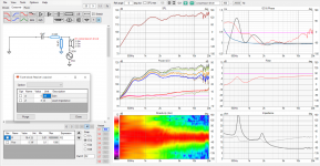
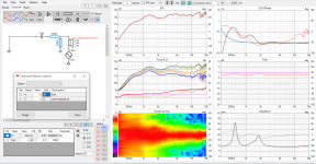
Here, source inline with driver to see impedance from driver side. Inductor lowers impedance for the driver and dampens the resonance.
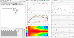
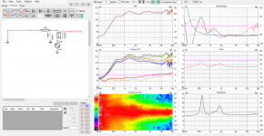
Here source as usual. Inductor works as high pass of course, damped resonance.
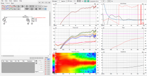
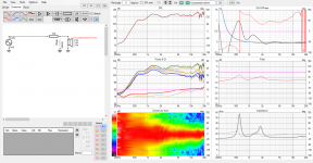
Here capacitor and L pad for comparison, levels and slopes not adjusted to match. L pad has 8ohm resistor, much higher impedance for the driver than the 0,1ohm resistance in the inductor.
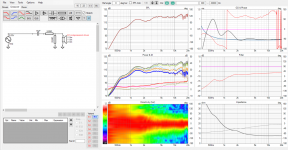
To untrained eye it looks like the parallel inductor, while providing high pass, provides better damping for the driver than series capacitor high pass (with L-pad). Looking from amplifier side capacitor would make high impedance (for lows) and the other would just be about 10ohm for most part.


Here source as usual. Inductor works as high pass of course, damped resonance.


Here capacitor and L pad for comparison, levels and slopes not adjusted to match. L pad has 8ohm resistor, much higher impedance for the driver than the 0,1ohm resistance in the inductor.

To untrained eye it looks like the parallel inductor, while providing high pass, provides better damping for the driver than series capacitor high pass (with L-pad). Looking from amplifier side capacitor would make high impedance (for lows) and the other would just be about 10ohm for most part.
Last edited:
The funny thing is low noise amlification is related to bandwith, eg crossover point of the amps amp HF filter. It is dependent of root of bandwithBut, we could just assume/strive for low noise amplification and not stress about it too much in crossover context I think.
So LC lowpass filter in amp or at speakerelement is a cheap way of low noise amplification.
Normal amps has LC filter at say 40 kHz
If this is lowered in a SUB amp to 400 Hz in the amp or at the woofer, The bandwith is 1/100. And noise is decreased by 1/10 or 20dB. And most important, the noise where the ear is most sensitive is lowered.
Somehow I though noise would be about constant no matter frequency, is there different kind of noises?😀 I guess the total would drop as bandwidth is reduced, hmm, is it because there is more power in music in lows that makes the difference or whats the relationship? sorry I don't know too much about amplifiers... just trying to make sense of it, why noise drops more than "content" 🙂
But that high impedance created by the capacitor reduces the damping factor (look at the humps in the filter response), that's why series capacitor is not recommended in high-SPL situations with horn loaded drivers if another high-SPL source (a midrange driver for example) is close to it. Yes, the horn start to acts as a microphone and the loaded driver starts to move. The diaphragm even can hit the phaseplug and shatter.To untrained eye it looks like the parallel inductor, while providing high pass, provides better damping for the driver than series capacitor high pass (with L-pad). Looking from amplifier side capacitor would make high impedance (for lows) and the other would just be about 10ohm for most part.
Last edited:
I see, on high power application there would not be a pad with the capacitor, no shunt, and no damping for the driver. Better damping on the compression driver might be audible even on low power use, if eventual crossover is low, I mean amplifier excites the driver resonance as well. With capacitor and L pad there is some damping but not as much as with the small parallel inductor.
Last edited:
Ok backing up a bit and looking the subject again from some distance.
When there is no components between (voltage) amp and driver on an active multiway speaker system then the driver always sees very low impedance (amplifier output impedance) and is well damped, all is golden without anything in between. But load for the amplifier varies with frequency and excursion.
We could add some components to try make the load impedance vary less, less in general and less with cone excursion, purifi example, make more stable load for amplifier, perhaps a hifi system use case.
We could add some utility components to the system, like protection for a compression driver/tweeter.
In case we added some components to the system to perform these various tasks we have to consider both the amplifier load and the driver damping and figure out impedance for both the amplifier and for the driver so that the amplifier is happy and sufficient damping of driver resonances happens.
Alright, is there more to it?
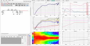
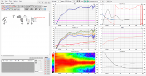
Here again, tried to match on axis response for 10uF cap with -6db L-pad and series resistor with shunt inductor. Its lots nicer response with the inductor, better damping for the driver. Need to try this one. Have to take new measurements as this is another waveguide and stuff. Thanks YSDR for this!🙂


Last edited:
Yes, the horn start to acts as a microphone and the loaded driver starts to move. The diaphragm even can hit the phaseplug and shatter.
Yes - in extreme cases it can lead to the distruction of diaphragms. But I hope that no one listens at such volumes at home. But it may probably still give an IMD advantage.
Regards
Charles
I have quite noisy cheap classD amp with too much gain now so noise is a problem. I have no idea if it would be better having passive xo just for the noise or not, havent tested it. Certainly better low noise amplificatiin will make big difference in case of sensitive speakers.
Wouldn't step numero One on the road to better sound quality be to get a better amplifier for that top end? 😀
Yes thats the first step 🙂 need protection for the tweeter still, but dont want to order any parts before taking measurements of current system. The ones I've been using in the thread are fron same driver but different horn so can't simulate whole system with it. Messurements I have for current system include cap and pad so not suitable for simulating passive parts 😀
Currently assembling some icepower modules into an enclosure, finally a stereo setup after finished, at least few more evenings as I have seemed to lost half of my tools during home rebovation few years back 😀 supposedly lower noise. DSP also changes, hopefully its better in this regard as well. I've been prototyping with Sure Wondom 2.1 setup, adau1701 DSP chip, suitable for 3way mono system, but noisy. Huge amount of utility but cheap price reflects its not very good design.
Currently assembling some icepower modules into an enclosure, finally a stereo setup after finished, at least few more evenings as I have seemed to lost half of my tools during home rebovation few years back 😀 supposedly lower noise. DSP also changes, hopefully its better in this regard as well. I've been prototyping with Sure Wondom 2.1 setup, adau1701 DSP chip, suitable for 3way mono system, but noisy. Huge amount of utility but cheap price reflects its not very good design.
Last edited:
We need to remember that _any_class D amp has an output LC filter. If you simulate one of these simply for FR, you'll note that without a load, it's completely under-damped. The damping part that prevents this filter from ringing is the 4, 8 Ohms speaker load. So with a resistive load on a class D amp - all is well regarding the output filter getting out of hand.
An ordinary speaker load with a passive 2, 3 way crossover? The load Z for sure isnt "8" across the board - and that output filter will respond accordingly. Now, unsure what it does to sound - must not be too bad - but I did read where TI cautions against letting the output filter under-damping get too wacky, lest it cause nuisance shutdowns, etc.
Example; you want to drive a bigger amp with your existing class-d output. A resistor attenuation, to bring the level down to line, right? Not without loading the output at 4, 8 Ohms too. Unless you tear out the LC and put the 4, 8 in series with the LC...
On the other hand, this may be - maybe - one of the reasons behind amps measuring so well when loaded resistively, then not as well when loaded with a pile of R's L's and C's. I'm sure that's true with all amps to some extent, which is why KEF endeavored to add "burner" networks into their crossovers, to keep the input appearance resistive. Net gain is sounds better with most any amplifier.
Knowing a number of such tricks, you can mix/match them as "appropriate" for each of the drivers / amps in your n-way system. If you're not using a driver near its own resonance, no need to be overly concerned with damping on that one perhaps... Maybe sounds better to give it a more HiZ drive?
I hope your resistor is a high power unit on a heat sink. Usually in passive filtration that means the resistor will see the entire bandwidth because it's before the crossover with a shunt path. Maybe you can correct me if I am wrong in this case.I am using a "sine-cap" passive filter for the CD+horn instead of L-pad+capacitor in a DSP crossover system. This consists a series resistor followed by an inductor to the ground, same as the Sonus Faber used in the Extrema's crossover. The filter is similar to a first order filter and an attenuator, but it damps well the resonance peak of the driver and can compensate the sloping down horn response and you have only a single resistor in the signal path without a capacitor. But be aware, the sine-cap filter actually is a shelf filter, it won't blocks DC, but can reduce it's level (if present).
I am using it in an active, DSP crossover based loudspeaker (as I stated earlier), so it's not passive.I hope your resistor is a high power unit on a heat sink. Usually in passive filtration that means the resistor will see the entire bandwidth because it's before the crossover with a shunt path. Maybe you can correct me if I am wrong in this case.
The 10W resistor (a normal one, without heatsink) was never even lukewarm in home environment. I check it regularly, because it's placed outside of the speaker enclosure, easily accessible for the fingers.
After the active xover then, got it.I am using it in an active, DSP crossover based loudspeaker (as I stated earlier), so it's not passive.
The 10W resistor (a normal one, without heatsink) was never even lukewarm in home environment. I check it regularly, because it's placed outside of the speaker enclosure, easily accessible for the fingers.
Yes. Several years ago I had a chance to listen to an amplifier with adjustable output impedance that another person brought to a Planet10 weekend listening party. I went home and figured out how to build my own. I used a cheap LM3886 chip amp board and modified the feedback loop. Connecting the negative terminal of the speaker to the amplifier with a 0.5 ohm resistor provides a current sensor. Then connecting a wire from the negative terminal of the speaker to the inverting input of the amplifier completes the current feedback loop. I tried it out using LTSpice before risking any hardware. To avoid problems at high frequencies, a series RC network can be applied across the speaker to limit the maximum impedance seen by the amplifier at high frequencies. The book on current drive of speakers I referenced gives good instruction on how to do it. As these amplifier boards were less than ten dollars each a few years ago, I built a pair of three channel transconductance "plate" amplifiers to put on the back of my speakers directly. A miniDSP 2x4HD on each speaker provides the filtering. The photo shows the three amplifier boards at the top, a capacitor board and two switching power supplies at the bottom. You can see the power resistors used for current sensing between the amplifier board and the terminal blocks for connecting to the drivers. Depending on the sensing resistor value the gain Amp / Volt of the amplifier is set.^^ Current drive / transconductance amplifiers are interesting but as they are relatively rare I have not come accross too much information about them. There seem to be some projects available on the forum but utilizing class D amplifiers for this would be cool, not sure if its something doable? I remember someone sayin Bruno Putzney tried /used one, perhaps some Hypex module, as current amplifier but thats also something. Hopefully something like that would become more common in future as class-D systems with all kinds of frontend stuff are more and more common, and seem to be quite good quality with low price point. But, I believe its problematic because the speaker /crossover needs to be paired with it, to go with a current amp? Perhaps it stays niche, and would be quite cool for us DIY folks to exlpore and enjoy. DSP based systems would seem good candidate for such amplifier.
Do you have current amp, worth it?
"Is it worth it" I think the effect depends on the driver. I expect a driver with significant variation in inductance with cone motion would have measurable reduction in distortion with a two tone test. Of course it is easy to measure levels of distortion that are far below audibility. I didn't record my test results when I built these. I may have to go do some measurements. They sound great. But every DIY speaker sounds great to the builder. Ha
- Home
- Loudspeakers
- Multi-Way
- Passive crossover parts in active speaker system? Possibilities of hybrid crossover