https://www.theengineeringknowledge.com/bridged-t-attenuator-configuration/Whats the benefit of bridged T over simple L-pad? Yes on hifi systems some kind of pad between amp and compression driver seems very logical, I'm using simple L-pad.
So it can balance impedance both ways. I'm not sure how this relates to crossovers, does it give more flexibility for crossovers or whats the benefit? how do you use it, is it for pairing some certain amp to some certain driver or whats the motivator using many more resistors than simple L pad?
Here was another resource https://www.electronics-tutorials.ws/attenuators/bridged-t-attenuator.html and there is the simple T and L attenuators if one scrolls to previous articles.
Here was another resource https://www.electronics-tutorials.ws/attenuators/bridged-t-attenuator.html and there is the simple T and L attenuators if one scrolls to previous articles.
Sure, since this is DIY you can do anything no manufacturer of a commercial product could afford. Along the KEF philosophy, whatever it takes to make the amplifier have an easier time driving; the amplifier feedback is there, but is doesnt have to do much as the speaker looks like a resistor across its frequency range. Or the Purify idea that there's less distortion if the driver sees a bit more than the speaker cable short circuit looking back from its terminals. Or transformers that convert an amplifier low Z to high Z to drive a VC. Or having 100W available to drive the tweeter - when 5 would do nicely - and you have all the voltage drop in the world to make the amp see that it's driving "nothing", or whatever it's ideal load would be for the lowest distortion, which may be a different value than 4, 8, 16, or open circuit.
I always use passive parts to pad and do the horn compensation on the my compression drivers in my active systems. Works just fine.
Rob 🙂
Rob 🙂
I am using a "sine-cap" passive filter for the CD+horn instead of L-pad+capacitor in a DSP crossover system. This consists a series resistor followed by an inductor to the ground, same as the Sonus Faber used in the Extrema's crossover. The filter is similar to a first order filter and an attenuator, but it damps well the resonance peak of the driver and can compensate the sloping down horn response and you have only a single resistor in the signal path without a capacitor. But be aware, the sine-cap filter actually is a shelf filter, it won't blocks DC, but can reduce it's level (if present).
You nailed it this is the motivation for the thread.Sure, since this is DIY you can do anything no manufacturer of a commercial product could afford. Along the KEF philosophy, whatever it takes to make the amplifier have an easier time driving; the amplifier feedback is there, but is doesnt have to do much as the speaker looks like a resistor across its frequency range. Or the Purify idea that there's less distortion if the driver sees a bit more than the speaker cable short circuit looking back from its terminals. Or transformers that convert an amplifier low Z to high Z to drive a VC. Or having 100W available to drive the tweeter - when 5 would do nicely - and you have all the voltage drop in the world to make the amp see that it's driving "nothing", or whatever it's ideal load would be for the lowest distortion, which may be a different value than 4, 8, 16, or open circuit.
If I'm interpreting responses so far what we can do, besides protection and noise suppression, is to try and dilute variable driver load behind some static values so the amplifier has easier time. Resistors would be best, applicable for highly efficient treble drivers, and woofers would benefit something else, like series inductor not to increase resistance much but to stabilize inductanse. Perhaps some shunt circuit helps the driver as well, like you refer, looking back to amplifier. It seems like its worth it to add some passive parts to an active system.
In Ellips-A project, fully active DSP based, I needed to solve protection of the tweeter. Mistakes happens, and broken Bliesma is not a nice thing. I have seen that in this case people uually use larger value capacitorin series with tweeter. Thank to Vituix I could model hybrid system, so I used small value capacitor, ~1.8uF, and this realized the linearization of tweeter+WG response. The rest of shaping was done by DSP. There are benefits of such a solution, small value of capacitor was not expensive and I could use Alumens which was a good match to Bliesma.
Years ago I had 100uF cap there on tweeter since that was the only I had 😀 since then purchased some 10uF caps and used one. This was also kind of out of crossover, just for protection. Now have few 10uf caps in series to make it more integral part of the crossover. Single 10uF alone was kind of bad, was hard to make xo with DSP, believe or not (there is effect to phase but not much for the pass band response), and most often was left with choice not have any high pass on the DSP which was introducing some audible distortion. Now with the cap starting slope much higher up there is no distortion and no need to use high pass filter on the DSP anymore.
Last edited:
If all elements are high sensitivity it does not help much to filter the highs of the woofer, I guess.On my three way system, 1" CD, 8" mid and 15" woofers, PA drivers, amplifier his/noise is audible from the CD and mid, not much on the woofer in comparison. CD has about 6db pad on it and its still perceptibly louder than whats coming from the mid, perhaps because it has wider polar response past few kilohertz, mid has falling power response due to beaming.
I have quite noisy cheap classD amp with too much gain now so noise is a problem. I have no idea if it would be better having passive xo just for the noise or not, havent tested it. Certainly better low noise amplificatiin will make big difference in case of sensitive speakers.
But in the case of pro woofer and the rest of the elements low sensitivity it can be worth it.
I note on passive damping of hf resonances. Sometimes they move by time and temperature. So the RLC filter should not be to high Q. (So the R has to be there in the filter🙂
It is also important to have some idea of the heat generated in the passive elements so they don't change value or break.
It is also important to have some idea of the heat generated in the passive elements so they don't change value or break.
^^ Noise is very interesting thing, check out dithering for example. Perhaps if there is noise on the mid driver and less so on the tweeter, or something like that, perhaps it affects perceived sound quality. Perhaps affects localizating the various ways from each other or something. But, we could just assume/strive for low noise amplification and not stress about it too much in crossover context I think.
BTW: I am not yet completely sure whether the Purify notch experiments are valid in general, and not individual amplfier (output configuration) dependant, even given the amps would all be Voltage Fb. and not CFB amps. CFB amps are a whole different kettle of fish.
Hi, what others have said + you can match the resistors to dampen the impedance peaks in the driver pretty well (as I mentioned in my original post). There’s a video by Joseph Crowe that I can’t find at the moment where he goes through this.So it can balance impedance both ways. I'm not sure how this relates to crossovers, does it give more flexibility for crossovers or whats the benefit? how do you use it, is it for pairing some certain amp to some certain driver or whats the motivator using many more resistors than simple L pad?
Here was another resource https://www.electronics-tutorials.ws/attenuators/bridged-t-attenuator.html and there is the simple T and L attenuators if one scrolls to previous articles.
I have gone from autoformers to L-pads and on to T-pads witch consecutively better results in sq.
Depending on the crossover topology that you want to implement actively you can use a capacitor before the L-pad (or T-pad or whatever type of voltage divider you are using) in order to get one highpass pole of your desired transfer function. This would give DC protection for free. While still not showing a perfectly frequency independant load impedance this would still be easier to dimension than if one were just using a series capacitor with the compression driver. And the driver does also "see" a lower source impedance at low frequencies compared to just a series capacitor. The low impedance source driving a compression driver is not so important at lower domestic playback levels but if they are close to loud woofer it will profit from it.Dunno if this counts, but I prefer to pad down compression drivers with a bridged balanced T-pad using wire wound resistors rather than decreasing the treble amp amplitude. Does stuff for the (often) complicated impedance curves on these devices that is only achievable through direct interaction with the driver.
Regards
Charles
Could you expand on this? So if there was only series capacitor on a compression driver there would be high source impedance at low frequencies, what does this mean in practice? When there is a L-pad in addition (between cap and driver) there is the shunt resistor which makes the low impedance for the driver looking towards amplifier, right? what this means in practice, how does this change performance of the driver in question?...
And the driver does also "see" a lower source impedance at low frequencies compared to just a series capacitor.
...
Do I understand this correctly, are you saying that a nearby sound source like a woofer would be "microphoned" through the compression driver if it has high impedance towards amplifier (at low frequencies)? basically the external sound would make the compression driver move some, which would then cause distortion for its bandwidth? When the compression driver inputs have some low impedance in place it damps the effect of this external sound pressure, resists movement? I guess if this is the case also resonances of the compression driver itself would be damped.The low impedance source driving a compression driver is not so important at lower domestic playback levels but if they are close to loud woofer it will profit from it.
Last edited:
I think it's better if the driver 'sees' a low impedance at resonance. Using your 10uF cap could interact quite a lot with a tweeter that as a low resonance frequency. You can easily see the effect if you simulate it in your XO design software using the correct impedance curve of the driver, and just compare with bypassing the cap.Could you expand on this? So if there was only series capacitor on a compression driver there would be high source impedance at low frequencies, what does this mean in practice? When there is a L-pad in addition there is the shunt resistor which makes the low impedance for the driver looking towards amplifier, right? what this means in practice, how does this change performance of the driver in question?
Do I understand this correctly, are you saying that a near by sound source like a woofer would be "microphoned" through the compression driver if it has high impedance towards amplifier? basically the external sound would make the compression driver move which would then cause distortion for its bandwidth? When the compression driver inputs have some low impedance in place it damps the effect of this external sound pressure, resists movement?
When it comes to 'hybrid' DSP/passive solution, I actually tried 'active woofer' on a 3-way speaker. Only DSP slope was on the woofer LP, and the mid + tweeter were fully passive XO. This improved bass a bit with less resistance in series with the woofer, and allowed me to fully time align the woofer to the mid. In short, it sounded better, but added more complexity, so I went back to fully passive.
^^ Oh alright, thinking what it means in practice, would following thought be about right? if I look at free air impedance plot of a driver, the peak(s) show the driver resonance, and basically we'd need some impedance between driver terminals that damps this, lowers the impedance peak? What the capacitor interaction means, is it just that the driver now resonates freely as there is no "damping" due to capacitor, high impedance between the terminals?
Few quick sims to aid. Flat impedance and measured impedance loaded in, interaction visible yes.
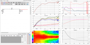
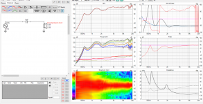
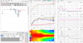
Then with l-pad and some variations to see what happens with the impedance peaks, interaction. It seems that as long as there is the shunt, impedance parallel to driver the impedance peaks get lessened, as seen as amplifier load?
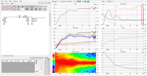
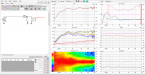
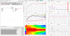
edit. trick from Purifi paper, how to see impedance what the driver sees back to amplifier by placing the source series with the driver (in VituixCAD). Shunt resistor on the L-pad makes lower impedance for the driver, the driver resonance is damped with the resistor providing lower impedance path to transfer the resonance to heat, right? the cap interaction reduces, which is not basically the capacitor that affects the driver itself, it just prevents damping happening on the amplifier output and the driver resonates naturally longer. Is this train of thought correct?
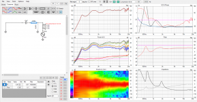
Few quick sims to aid. Flat impedance and measured impedance loaded in, interaction visible yes.


Then with l-pad and some variations to see what happens with the impedance peaks, interaction. It seems that as long as there is the shunt, impedance parallel to driver the impedance peaks get lessened, as seen as amplifier load?


edit. trick from Purifi paper, how to see impedance what the driver sees back to amplifier by placing the source series with the driver (in VituixCAD). Shunt resistor on the L-pad makes lower impedance for the driver, the driver resonance is damped with the resistor providing lower impedance path to transfer the resonance to heat, right? the cap interaction reduces, which is not basically the capacitor that affects the driver itself, it just prevents damping happening on the amplifier output and the driver resonates naturally longer. Is this train of thought correct?


Last edited:
Basically yes, but I think you can also get the same effect as you mentioned with the cap on the woofer. I have only scratched the surface by simulating it and correcting it when doing passive XO's.
How do you calculate a T-pad?Dunno if this counts, but I prefer to pad down compression drivers with a bridged balanced T-pad using wire wound resistors rather than decreasing the treble amp amplitude. Does stuff for the (often) complicated impedance curves on these devices that is only achievable through direct interaction with the driver.
- Home
- Loudspeakers
- Multi-Way
- Passive crossover parts in active speaker system? Possibilities of hybrid crossover