I see that. That's no good. Shouldn't NFB run to both halves of tube as well. Maybe to the two cathodes connections? Sorry learning as I go.
A few things wrong with the tail as drawn. The 12K tail resistor needs to be somewhat larger and not bypassed.
You would also want a gain stage before it.
The earlier stage as a concertina splitter was probably a better choice unless you want to add another gain stage.
You would also want a gain stage before it.
The earlier stage as a concertina splitter was probably a better choice unless you want to add another gain stage.
Please read up here: https://www.ampbooks.com/mobile/amplifier-calculators/feedback/
Too busy now to explain.
Too busy now to explain.
I was thinking the LTP, was a higher gain circuit? I will be using a preamp, so i don't need a ton of gain. Starting to think I should have started with a SE. Lol
I know, just makes things more complicated for my first real build. But I'll get there eventually, and maybe I'll have a little hair left.
A LTP roughly has half the gain of a comparable single triode stage. Hence, if you've got a double triode, a gain stage followed by a Concertina offers two times the gain of a LTP (but has other drawbacks), as does the paraphase.I was thinking the LTP, was a higher gain circuit?
Best regards!

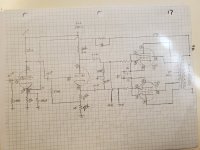
The EL34 will not have a grid leak resistor. They call it a stopper resistor in this case. It is meant to limit very high frequencies from getting to the power tube and causing stability issues. Should be about 1K. The resistors on the phase splitter should match 30K should work.
One reason to drop 50 volts between the phase splitter and the first gain stage to to any coupling between stages as far as plate supply.
One reason to drop 50 volts between the phase splitter and the first gain stage to to any coupling between stages as far as plate supply.
I originally had the first stage at 300. But the +/- voltage swings look better at 350. Maybe I shouldn't worry, but I was trying to get to 200v peak to peak for the el34s. Also knowing I'll loose a little in the phase splitter stage. Also, I was thinking the 2 risisters on the cathode would add together. Is that not how it works? So 29.5, and 30.
The feedback is shorted to ground by the 100 uF bypass capacitor. Split the 2k resistor into 1.8k and 220 ohms. Bypass the 1.8k with the 100 uF, and below that have the 220 ohms. Feedback connects to the junction of the 1.8k and 220 ohm resistors.
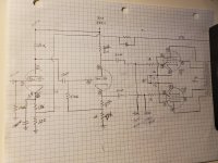
The feedback resistor should be fine. Remember to change the 27K cathode side of the splitter to 30K. You might try without feedback at first and add about 5-10K for feedback and see how many DB was dropped. You might need a tone generator which can be done with any computer. Also REW can run frequency response and distortion plots easily.
Also you want to add a pair of 270K bias resistors and tie them together and send to the bias pot.
Also you want to add a pair of 270K bias resistors and tie them together and send to the bias pot.
Would I tie them together if I am biasing each el34 individually? Or just put a 270k in each line from the bias supply?
You can bias individually if you want. Some use a matched pair and consider biasing the pair enough.
Are matched pairs generally matched well enough? Im looking at it from a stand point that it's only one more pot. Seems the adjustment available would be worth it?
The EL34 will not have a grid leak resistor.
With a power tube using fixed bias the resistor between grid and negative bias supply acts as grid leak.
Has nothing to do with the grid stopper.
There always needs to be a DC path for the grid leak current.
- Home
- Amplifiers
- Tubes / Valves
- Organ amp conversion