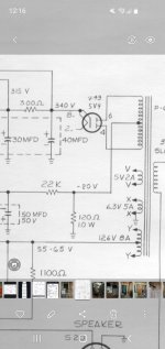
Not a 20V tap, but a real CT.Going by the schematic, the center tap leads to the 120ohm resister. But shows as -20 volts? Would the center tap actually be a 20v tap? And not have a center. But dc resistance is equal to each HV lead?
The amp uses "back biasing" to generate the negative bias voltage.
https://www.aikenamps.com/index.php/what-is-back-biasing
The center tap is usually tied to ground. In order to derive a negative voltage to bias assorted stages they inserted a resistor and capacitor on the negative side.
There is not really a 20v tap in any way.
red/Yellow to yellow should measure close to 700 volts. Measure with clips and not be holding anything when checking.
There is not really a 20v tap in any way.
red/Yellow to yellow should measure close to 700 volts. Measure with clips and not be holding anything when checking.
You do not want to measure HV with a scope. Maybe with a better meter. Also it is easy to get the wrong yellow involved considering you can mistake a 5V winding for HV.
Yep bad meter, scope shows 667volts. Time to pitch the old, really old flute.

Might be worth having a look at the Dyna ST 70 schematic.
You can keep the 6sn7 driver for the most part. You may want a preamp with a gain of about four though.
You may also want to see how this sounds as push-pull triode.
You are looking for an OT made for 30-35 Watts 4.3K - 5K or so plate to plate.
The choke listed in the ST70 schematic cam be replaced with a 30 ohm resistor. A pair of 1n4007s could replace the GZ34. You would get negative bias from another pair of 1n4007s with cathode facing the transformer and use a voltage divider to get to about -50 volts.
Attachments
Sounds like a plan, should provide plenty of power. And I'd rather do 2 el34. Rather than 4 6l6s. This PT, has 3 6.3volt leads, one is 12.6 with center tap. Would it be over kill to give each tube it own 6.3v. ?
Knowing my speakers are 6.5 ohm impedance or so, would probably better get the slightly larger input impedance.
Was the 12.6 really comprised of a pair of 6.3s? A pair of EL34s and a 6sn7 comes out to 3.6A so you could use the original. You can use the 12.6 to run the EL34s if you want to play the overkill game. Sort of a bit of extra current to spare here.
Yep, 12.6 with center. And a separate 6.3. A 5v, and the HV. 12.6 is 8 amp. 6.3 is 5amp. So all kinds of choices. Thought about rectifying the 12.6, to neg dc, but won't be enough for bias voltage?
I wonder, could I somehow combine the 12.6, and the unused 5, to net 17.6 ac. Or maybe convert both to dc. Then stack them. ? Maybe a dumb question?
I was just looking at that, looks like a full wave voltage multiplier would work. And the 12.6 output at 8amps would have no problem at all. I could probably triple it or more with the amps available. But I'll have defeat my biggest enemy, MATH. Lol
Question for anyone following along, which would be better, all three tubes having its own 6.3v heater supply. Or power the tubes of the 6.3 main heater supply, and using the 12.6v stepped up for bias supply? Main heater 6.3 is 5 amp. The 12.6 is 8 amp, so can be 2 , 6.3v at 4 amp each.
I tend to agree, and much simpler. And the heater supplies will not even break a sweat.
- Home
- Amplifiers
- Tubes / Valves
- Organ amp conversion