
Mostly looks good though that bypass cap on the cathode of the first stage means the negative feedback will not work. You can go two different ways to fix it.
1- Just put the cap across the 2.4K resistor.
2- change the cathode resistor to 2.6k or so, attach the 10-K NFB resistor to the cathode and use as non-bypassed stage. There will be slightly less overall gain.
Option 1 is probably best to keep enough gain.
I would also drop the first stage voltage to 300 volts. Mostly to reduce ripple further as you deal with smaller signals.
First stage current should be about 1/2 supply voltage/plate resistor or 150/68000 or 2.2 ma. Dropping 50 volts would be about 22K.
You might want to re calculate the first stage values considering a drop from 350 volts to 300. Might be a trivial change though.
Last edited:
I originally ran the numbers at 300v on the first stage. But I was concerned with the ac operating range. It was well short of 200v peak to peak. At 350v it comes up just short of that number. I was thinking for some reason, 200 would be best. Am I wrong to think this?
Notice the splitter stage is effectively swinging twice the voltage compared to the first stage once you add up both sides. It would effectively need twice the plate voltage to keep up.
Consider the output tubes will be biased somewhere about -35 volts. 200 volts peak to peak should be fine.
One finer point is you want to raise the heater voltage on the 6sn7 maybe by 75 volts to avoid having too high of heater to cathode voltage on the splitter.
Also when mounting the output transformer try to have a fairly short path between the entry point on the chassis and the tube sockets at least for the plate and screen wiring. Having them too close to the driver stage can cause stability problems.
Ok, so I lowered first stage to 320v, adjusted Q. Point, 2.5ma 140v. Nets almost exactly 200v peak to peak. As far as the bypassing the 2.4k on the phase splitter, are you saying to to bypass it to ground? Or just across the resister? Sorry for all the stupid questions.
Attachments
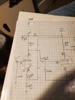
I meant 2.4K on the first stage if you did not want to bypass it. In this case you can bypass the gain stage with the positive side of the cap going to pin 3 and negative to the junction between the 2.2K resistor and the 220 ohm resistor.

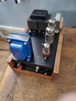
Looks good. Might be worth measuring for output if you have a load resistor.
If you have an assortment of resistors lying around I would try 20K and 10K and just have a listen.
You may need a scope to find compensation cap values or maybe look around at other amp schematics.
If you have an assortment of resistors lying around I would try 20K and 10K and just have a listen.
You may need a scope to find compensation cap values or maybe look around at other amp schematics.
Will do, I ran them up to clipping with a 8ohm load, 14+volts. I also put in a small tag strip just for the feedback. That way I can change parts super easy. I'm also running on low side for bias. Tubes in one don't seem well matched. May end just need some time?
Did you go with a bias pot for each tube or the pair?
You may want to double check the resistors between cathode and ground and make sure they really match.
A day or so of burn in time should be enough before checking tubes for matching.
Also matching could be off if you are a little low on bias. Also it is possible for matched pairs of tubes to not really be matched.
Thanks, tubes have all of 5 minutes on them, so I'm sure they will change. And I will change resistors for checking the bias. Don't trust them.
Oh, and went with one pot for the two. I also haven't swapped tubes yet, so maybe I messed something?
In the case of one pot for the pair, swapping tubes would just tell you if there is a bias imbalance caused by parts other than the tubes like a leaky coupling cap or drifted resistor.
Quick question for anyone following. I've been working on testing my amps with REW. And not sure I'm doing it correctly. Running output from audio interface to amp, then out to dummy load. Tying into it with a 10-1 voltage divider and back to input of rew. Runs sweeps as one would expect. But I've changed the values in the gnfd circuit a hundred times, and barely changes anything. 5k 220pf, is nearly the same as 1meg 80pf. ??? 1% thd. With no fb. .7% with 150k 220pf. At 1 watt. ???
Ok so I figured out I had my settings all botched up. 1st, was testing at 4watts. Not 1. And ran the step test. Thd+N= 0.13% almost all 2nd order. I'll work on nfb from here.
I forgot to ask. When you say there is some bias mismatch between tubes how much do you see? Matching for tubes may be at some specific bias current and voltage. Also not likely to match withing something like 1%.
- Home
- Amplifiers
- Tubes / Valves
- Organ amp conversion