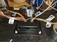
2.5V may be half of a center tapped 5V winding for a rectifier tube filament. I'd separate all of the windings that have
continuity and go from there. Super low resistance = filament. May even be green. Higher resistance = high voltage/plate etc.
You should be able to find a schematic online which would help simplify things a bit. Hope this helps.
continuity and go from there. Super low resistance = filament. May even be green. Higher resistance = high voltage/plate etc.
You should be able to find a schematic online which would help simplify things a bit. Hope this helps.
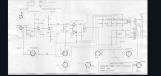
You can guess how much current the assorted other tubes pulled as far as plate current. That step down from 315v to 295v over 300 ohms would be 67 ma. I am looking at the 300 ohm resistor between the 30 microfarad caps. It is about 20 watts consumed constantly which is now gone. A little is for the 6sn7 in the amplifier but not nearly that much. It is hard to guess how much power the 6v6s provided without knowing the output transformer impedance. Rough guess is 10-15 watts. Anyway, the power transformer should support 20 watts easily and possibly a little more if you ditched the rectifier tube and more if you went fixed bias.

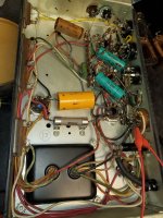
Yeah, I'm thinking of going SS rec. And UL output transformer. Maybe quad 6v6, or pair of 6l6. I'll have to see what my B+ will be without all the DC brop resister that aren't needed anymore. Just pulled the power transformer out of chassis. I'll check voltage with it isolated.
Use a silicon bridge , use a divider to get -20 volts bias. B+ will then be over 400 volts.
I have to say you do get close to enough voltage for EL-34s if you went fixed bias and dropped the tube rectifier.
Plate voltage would be too high for 6v6s. You can get close to 20 w UL with 6l6/5881s.
EL34s will have slightly less on resistance and push you closer to 25-30 W.
A quad of 6L6/5881 is another option.
The difference in on resistance between tubes is mostly driven by how much heater current is used.
6v6 is .45
6l6/5881 is .9 and EL34 is 1.5
As far as asking if the power transformer will support it, you have to consider you lost 20 watts from the plate supply that went for the extra tubes. I would guess the extra tubes drew 5A from the 12.6 volt tap giving 63 watts lost.
Before you buy output transformers you may want to be sure the power transformers are good by at least applying power to them for a few hours and make sure they do not get hot.
Make sure all leads are well insulated. Also if they get slightly hot you may have to ask if the line voltage is too high. Looks like rated supply voltage is 115v in the schematic. Most US domestic power is 120 v. You may be forced to drop a few volts if they get hot due to excessive input voltage.
Great insight, thank you, I was thinking I could get more voltage, but wasn't sure about current. But the more I research, looks like a ton of load will be eliminated from the PS, without the rest of the organ being used.
Seems to me that 400v available you could probably run 6l6s at a conservative bias point and get well in excess of 20 watts using an ultralinear transformer like the TO-300.
I've got some which run a bit higher B+ and they run up to about 35 watts before clipping.
Do you have the ability to check how much current your High voltage winding can deliver?
What rectifier did it use? That will be a major clue as to how much B+ current you have available.
There's no substitute for iron and copper when building a tube amp propper.
In the stock trim, it used a 5v4 rectifier. Out of circuit and no dim bulb, HV side is 345v to center tap per side. Still unsure of current capacity, but if I had to guess, judging by size, it should have plenty for more power. Just unsure how much B+ I'll be able to get?
Yet another question, it seems my PT HV winding from one side of center tap is out of phase from the other. So reads 2volt across the whole winding. Will this cause issues with rectifier? Planning on going with full wave SS. Thanks for input from everyone.
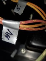
What colors are they? Wondering if wires are faded and hard to tell. Also remember general HV safety when playing with these things.
Guessing they should be red-red with red-yellow being center tap.
Guessing they should be red-red with red-yellow being center tap.
Also have a unit without the transformer removed? Would help to get a shot of the bottom of the rectifier socket.
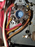
This thing is not following typical color codes for wiring. From the second picture we can be sure that the red with a little yellow stripe is the HV CT. Normally both sides of the HV would be solid red. CT would be yellow with a red stripe.
There is a chance that the wires are mis-grouped in the first picture. Are you sure there is continuity between all three wires for the HV? The 5V winding may be swapped.
Common Black
Tap Black / Yellow
End Black / Red
High Voltage Winding Red
(center tap) Red / Yellow
Rectifier Filament Winding Yellow
(center tap) Yellow / Blue
Filament Winding #1 Green Usually 6.3v
(center tap) Green / Yellow
Filament Winding #2 Brown
(center tap) Brown / Yellow
Filament Winding #3 Slate
(center tap) Slate / Yellow
- Home
- Amplifiers
- Tubes / Valves
- Organ amp conversion