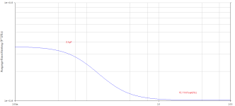
Just noticed that the C1 suggested 470nF has a lot of impedance at low frequencies (17k at 20Hz) - best if it were say 10µF or more, then you won't have to worry about the 1/f current noise of the input transistor generating avoidable input noise across C1.
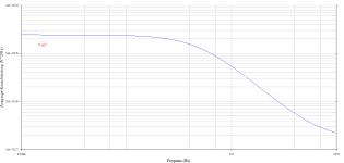
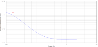
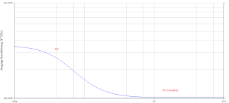
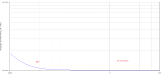
It is easy to simulate the inherent noise at the input node, the base electrodes of the transistors.
Let's take a look at what is generated at f=20Hz.
7,1nV / sqrt(Hz) , 20Hz
...
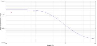
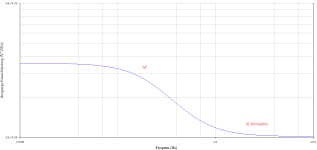
4,2nV / sqrt(Hz) , 20Hz
We recognize the attenuation curve of a 1st order high-pass filter. No more and no less.
Attachments
Last edited:
If I'm talking nonsense, it's because of the heatwave and the total lack of restful sleep - I apologize.
470nF, 1µF, 2µ2, 4µ7, 10µ, 22µ, 47µ ... none of these values present a real problem in terms of additional 1/f noise.
I can only make one recommendation:
contact catd and order a board, set up the EQ and enjoy your TT with an inexpensive MM.
Bye,
HBt.
470nF, 1µF, 2µ2, 4µ7, 10µ, 22µ, 47µ ... none of these values present a real problem in terms of additional 1/f noise.
I can only make one recommendation:
contact catd and order a board, set up the EQ and enjoy your TT with an inexpensive MM.
Bye,
HBt.

(...) about the 1/f current noise of the input transistor generating avoidable input noise across C1.
Ok,
"Current" is equal
to voltage divided by effective resistance or the resulting impedance (?)
- active, effective = constant
- impedance is a function of frequency and value of C and R
I decreases with increasing Z -----> but ... "Voltage" is I * R ... but I_noise * -jXc is not ...
Shitty climate change,
HBt.
(who can no longer sleep)
If I am writing nonsense, I apologize right away as a precaution. Put it down to the consequences of man-made climate change, because I am one of those creatures that suffer extremely from the heat (I need a cool habitat, with moderate fluctuations, adaptations).
#
I suspect the recent comment from a user is about the typical noise, behavior of a bipolar transistor at low frequencies.
Looking at the equivalent circuit of this case, or modulating it, we find five noise sources, two u_noise and three i_noise. The so-called excess noise is now attempted to be described with the help of the basic shot noise. Experimentally, our forefathers have determined that the current noise of a transistor increases at low frequencies (and this is what the egg dance is all about, digression) with 10dB per frequency decade (to the left). There is simply nothing we can do about this, except perhaps find a transistor that is better suited than a BC5xx, or ...
Consider 470nF simply as a small subsonic filter directly before the amplification and 47µF as a practical short circuit -> in the end it is a coupling capacitor that keeps possible DC voltages away from the MM and also randomly injected DC voltages away from the amplifier.
From a practical value of 4.7µF (a nice little WIMA MKS and a 10nF WIMA FKP in parallel), nobody has to worry about generating terrible, nasty, low-frequency noise.
If an electrolytic capacitor is used as a coupling capacitor at this point, it should be larger than 17µF. 22µF/63Vdc would be the value of my choice, it must not be smaller and it may also be a 100V type as dielectric strength. Why is this the case? is slowly going beyond the scope of this excursus.
Please do not worry about this coupling capacitor at the first position within the entire signal processing chain.
4.7µF as a foil /or 470nF as a foil if you want to establish a small first subsonic filter just before ultra-low frequencies are amplified.
Bye,
HBt.
@hbtaudio It seems You over worked this problem 🙂 We were just speculating. I'm greatful for Your thorough investigation and explanation though. My reflection is that this kind of a "issue" would have been impossible to discover or analyze two decades ago. The simulation tools available are a fantastic and certainly make for better designs. I remember at university I was doing iterative calculations in excess of 12 hours to dimension a three transistor small signal amplifier 😀
Then you are armed with sufficient specialist knowledge.at university I was doing iterative calculations in excess of 12 hours to dimension a three transistor small signal amplifier
😉
I simply did not want the heckling from the podium to lead to completely useless uncertainty. OREAD is a project that aims to give us the joy of crafting (again).
You can assume that this area was already solved eons ago by the superposition principle alone. But, of course you are right, SPICE is a blessing. Just like measurement technology. But without the mathematics (the mathematicians) - applied calculations, ... we are nothing.would have been impossible to discover or analyze two decades ago
What is your Cp doing? Have you already shortened the line accordingly (< 0.5m) - is your MM system now correctly terminated.
Let's just let OREAD speak for him-/herself 😉.
kind regards,
HBt.
I'm sorry, but work and other private stuff has come inbetween. I will try measuring the tonearm to OREAD interconnect during the weekend. We have nice weather here where I live for a change and I will probably use the opportunity to take one of my bicycles for a ride too, so I regret to say OREAD will probably have to stand back a day or so.
When I know the capacitance of the interconnect I will decide what I need to do to get the cartridge loading right.
I also have to pull myself together to build the enclosure.
When I know the capacitance of the interconnect I will decide what I need to do to get the cartridge loading right.
I also have to pull myself together to build the enclosure.
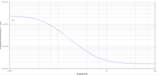
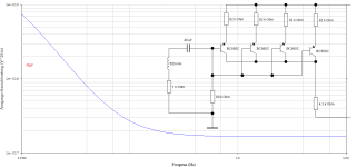
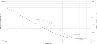
Let's look at the output node and consider the inherent noise (from 20Hz upwards) as a function of the coupling capacitor.
Attachments
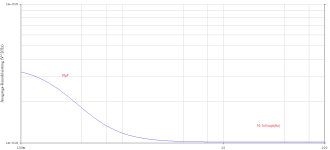
If we want to know which quasi noise current in the input circuit, i.e. at the effective resistance of the system, is a... constant horizontal line over the low frequencyband 1Hz to 100Hz ... independent of the reactance of the capacitorin the range of 470nF to 40µF:
4.123pA/sqrt(Hz)
The coupling capacitor is not a noise amplifier.
4.123pA/sqrt(Hz)
The coupling capacitor is not a noise amplifier.
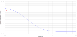
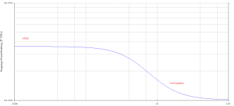
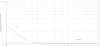
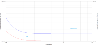
Now with MM as the noise source - but of course this is not the 1/f current noise of the emitter base sections.
But our two setups (catd & hbtaudio) work perfectly.
Value 470nF as a coupling capacitor value should be interpreted as a subsonic filter. Point around.
But our two setups (catd & hbtaudio) work perfectly.
Value 470nF as a coupling capacitor value should be interpreted as a subsonic filter. Point around.
Attachments
So, what You are saying is I should replace my 4,7 uF coupling capacitor by a 470 NF one as a subsonic filter?470nF as a coupling capacitor value should be interpreted as a subsonic filter
(As I'm using a DSP crossover it's easy to add e.g. a third order high pass Bessel filter at say 12 Hz on the output (if I don't already have something similar)
Precisely:
small values for the first coupling capacitor indicate (and define) a lower cut-off frequency.
You can like this or opt for 22µ to 47µ - all without any harm. The question is, why should the lowest interference be amplified by a factor of 1000?
small values for the first coupling capacitor indicate (and define) a lower cut-off frequency.
You can like this or opt for 22µ to 47µ - all without any harm. The question is, why should the lowest interference be amplified by a factor of 1000?
More important in your case seems to me to be
a) the line capacitance
and
b) the (perhaps absolutely necessary) buffer between OREAD and your DSP (Najda) input.
But now I have to go to the cemetery to visit my relatives - I'm in a hurry,
HBt.
a) the line capacitance
and
b) the (perhaps absolutely necessary) buffer between OREAD and your DSP (Najda) input.
But now I have to go to the cemetery to visit my relatives - I'm in a hurry,
HBt.
You have to stop me if I use this space to iterate over my own problems too much. Maybe there is a different thread for the below discussion. I still think it can be of general interest in the context of RIAA compensation.
I measured the tonearm to OREAD interconnect (It's the SME original cable that came with the tonearm, a SME Series III ). It's about 280pF for about 1,2 meter i.e. of the same magnitude of the OREAD to preamplifier interconnect, 540pF. As a reference I looked up RG58 which has a capacity of 82pF/m while a UTP Cat 6A sports 40pF/m. In that light 230pF/m seems excessive.
I'm not well read up on cable capacitance and termination. To me a coax termination is usually pure resistive at 50 - 75 ohm. I don't know if a 47pF capacitor at the end of a cable imposes a different load on the signal source (cartridge) as the same capacitance over the whole cable?
It's no problem for me if we briefly talk about lines and cables here.
I don't know if I'm being too forward now, but if your MM system would like to be terminated with a few pF ||47kOhm, it may be right to shorten the SME cable to well < 1m.
With RG coaxial cables, the characteristic impedance is interesting in a completely different respect, namely for reflection-free transmission of a carrier, however modulated and coded.
But, if you now connect your LCR meter to the end of the connection line and it shows a Cp (at 10kHz measurement frequency or 1kHz) of >200pF without an installed system, then I would shorten the line or use an MC.
I don't know if I'm being too forward now, but if your MM system would like to be terminated with a few pF ||47kOhm, it may be right to shorten the SME cable to well < 1m.
With RG coaxial cables, the characteristic impedance is interesting in a completely different respect, namely for reflection-free transmission of a carrier, however modulated and coded.
... consider it as identical - as we are looking at audio frequencies, absolute low-frequency activity. "Die Leitungstheorie" is practically irrelevant here at lengths of 1 m and used frequency.I don't know if a 47pF capacitor at the end of a cable imposes a different load on the signal source (cartridge) as the same capacitance over the whole cable?
But, if you now connect your LCR meter to the end of the connection line and it shows a Cp (at 10kHz measurement frequency or 1kHz) of >200pF without an installed system, then I would shorten the line or use an MC.
On the output side, it may be necessary to reduce the C6=2.2nF to 1nF or 470pF; but I recommend an impedance converter at this point, for your local application.
Assuming I have a correct picture of the conditions on site in my head. Catd use 10nF without any Problems, as I see.
Assuming I have a correct picture of the conditions on site in my head. Catd use 10nF without any Problems, as I see.
😀 You could speculate that the vastly different impedance of a MC to a MM has a large influence on why audiophiles prefer MC pickups.shorten the line or use an MC
This is the first time in 32 years that I have listened (again) to an MM system.
And the small, very inexpensive blue AT system really knocks my socks off. Maybe it's the OREAD and the correct termination.
In electrical terms, it is the impedance, i.e. the internal generator resistance, that catapults the MC to the top.
However, this would no longer play such a significant role if at least the first stage (ideally even designed with jFet) could be placed directly at the end of the tonearm cabling. For example, as Nick Sukhov has been doing since the very early 1980s until today.
- Home
- Source & Line
- Analogue Source
- Oread - a DIY MM phono approach