PNP's can be lower noise though. The obsolete 2SB737 being an example, at 100uA collector current about 0.3pA/√Hz, and at 5mA about 0.4nV/√Hz...

🙂 I am looking forward to your assessment.I will refrain from opinions until I've got OREAD working.
We can't really give a general answer to that.Maybe I can read it in the thread, but isn't it more conventional using NPN's for the differential input stage?
However, with the OREAD project (topology) you /we are basically free in your /our choice.
Enjoy it just as it is.
kind regards,
HBt.
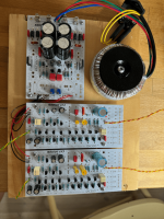
Last Friday I did a test assembly on a wooden board. This didn't work out well. Only got some hum on the outputs and the negative fuse went after like a minute even if nothing heated up. When there's time again I will inspect and connect one OREAD at a time to the P/S to work out what is wrong. Worst case I do have an old oscilloscope... but it's probably just some silly mistake on my behalf.
Attachments
How can I /we help you?
I hope you find the error quickly and it has no consequences for the EQ.
Strange and sad.
I hope you find the error quickly and it has no consequences for the EQ.
- Always test the power supply alone and first
- Check again that you have inserted the correct order of PNP or NPN on the OREAD boards; an accidental swap is not unlikely
- But somehow the scenario sounds like a short circuit.
Strange and sad.
Thanks for Your concern, I'm convinced it's my fault. I'm not at home, so You will have to endure until I've had time to look at it again. As You suggest I can very well have mixed up the transistors. I did test the P/S separately and it worked flawlessly, with its soft start.Strange and sad.
I'm writing to keep the thread alive and hopefully encourage more adopters. I hope writing about "obstacles" rather helps other avoid my mistakes than discourage. I'll write again when there's anything to report
As far as I can tell from your picture,
1.) you have not connected the ground planes GC of the boards.
They should be connected to GS/ground, otherwise there may be oscillations, at least if there is no shielding housing.
2.) you have left out the capacitors on the outputs of the power supply.
As far as I know, the LM337 in particular is a bit finicky if it doesn't have an output capacitor.
So there should be at least small capacitors (e.g. 1µF).
But I don't know if that has anything to do with your problem.
First test the power supply by running it with and without an appropriate load (e.g. 500mA) and measure whether the regulation works, i.e. whether the output voltage remains constant.
When running the OREAD, measure the current consumption of one circuit/board, which should be around 2.5 mA at each voltage/rail. (at +/-15V)
To be on the safe side, you could also test the OREAD with two 9V batteries first to possibly avoid blowing anything in the event of an error.
Then there will be 1.3mA per rail, per board
Last edited:

Excactly this was the problem. A spare 47uF I had lying around was used to prove Your point. I have encountered the same problem before, but I thought the capacities on the OREAD board would be enough. Apparently not. Without any load it measures 15V, but as soon I loaded the -15V it dropped to around -2 - -3 V. After adding the capacitor the voltage had to be readjusted. The positive regulator is more fault tolerant.2.) you have left out the capacitors on the outputs of the power supply.
As far as I know, the LM337 in particular is a bit finicky if it doesn't have an output capacitor.
So there should be at least small capacitors (e.g. 1µF).
You are also right about RB being soldered on the underside of the PCB.
I didn't bother about the GC connection for now. Proper shielding will not be provided until I've built an enclosure anyway. I do appreciate You have provided the wiring of the complete circuit including P/S and enclosure. I consider following Your instructions better this time 😀
Now the P/S and both boards are working. Because the experimental setup and I haven't pursued any listening evaluation.
Next thing will be crafting a box and mounting the amplifier. This will probably take me some longer than building the electronics.
Many thanks for Your concerns and helping me!
I will complete the MM version before jumping onto a MC variant, but I'm interested. I see You've changed the output stage of OREAD, in my eyes to simplifiy building it, fewer components?
Last edited:
small cause, big effect 🙂Now the P/S and both boards are working.
congratulations that everything is working now. 👍
MC is just a simulation. I don't have an MC pickup system for real testing.I see You've changed the output stage of OREAD, in my eyes to simplifiy building it, fewer components?
The output stage with single transistors is also just a test. The output stage contributes relatively little to the noise of the circuit, so here the paralleling of transistors is more of a high-end cosmetic.
But I haven't really thought about simplifying by reducing the number of components, although on the other hand that might free up board space to accommodate the MC stage parts and keep the board size.
But these are all just thought experiments while I wait for the new OREAD boards. I want to build the current circuit version with the polarity reversed first, so with an NPN input stage.
I don't own a MC cartridge either, so You researching reversed polarity is probably closer to home for me 🙂 A pre pre amplifier is certainly less expensive than a Step Up Transformer, but the latter would be an alternate solution if one wants to use OREAD from a MC signal.I want to build the current circuit version with the polarity reversed first, so with an NPN input stage.
The other families of negative voltage regulators are also critical. One more reason to operate an EQ via only one voltage source (as originally intended).
OREAD MM EQ
works and has not been damaged?
Regarding
MC pre-preamplifier, I can make some suggestions if you /we wish - it's not rocket science.
OREAD MM EQ
works and has not been damaged?
Regarding
MC pre-preamplifier, I can make some suggestions if you /we wish - it's not rocket science.
One can connect the outputs of two identical regulator circuits with positive regulators in series to obtain a symmetrical +/- operating voltage.The other families of negative voltage regulators are also critical.
This is how all my regulated power supplies for power amplifiers work.
I have also considered whether it would be better to modify the power supply board of the NT218 in this way, i.e. to design it for two LM317 or other positive regulators in order to avoid the negative regulators.
On the other hand, if you take the peculiarities of the negative regulators into account in the circuit design and follow the application instructions in the data sheets, they also work perfectly.
Are phono or power supply pcb boards available for shipping to US or is the cost too high? I have been in audio electronics for over 50 years. I own or have built the following: M cubed, CK3III, AKG K702, Thornes TD165, Yamaha C-85, Yamaha T-70, Tandberg TD-20A, Ortofon OM30, Pete Millett Nutube 50w amps, Pete Millett Sangaku Headphone amp, Pete Millett NuHybrid Headphone amp, Audioligica PPA Project headphone amp, Cavalli Bijou Tube Headphone amp, Cavalli EHHA Hybrid Headphone amp, Carvalli SOHA II Headphone amp, Douglas Self Phono preamp and O2 Objective Headphone amp. I enjoy building and listening to new designs.
Thanks
Bob
Thanks
Bob
I will ship anywhere you want and DHL delivers.
Everyone has to decide for themselves whether shipping is too expensive.
For example: DHL shipping costs for "small packages" to the USA are €12 without tracking; with tracking €16.
Customs fees may also apply in the respective recipient country.
If you are interested, please send a PM for further arrangements.
Hi, I actually use my CK3III as a treble amplifier at the moment. My AKG K702's are worn out. Wellcome to this project! This encourages me to get the case built. I'll try to get the material needed this weekendI own or have built the following: M cubed, CK3III, AKG K702
- Home
- Source & Line
- Analogue Source
- Oread - a DIY MM phono approach